IRF620PBF * Lead-Free www.irf.com 1 12/5/03 IRF620PBF 2 www.irf.com IRF620PBF www.irf.com 3 IRF620PBF 4 www.irf.com IRF620PBF www.irf.com 5 IRF620PBF 6 www.irf.com IRF620PBF TO-220AB Package Outline Dimensions are shown in millimeters (inches) 10.54 (.415) 10.29 (.405) 2.87 (.113) 2.62 (.103) -B- 3.78 (.149) 3.54 (.139) 4.69 (.185) 4.20 (.165) -A- 1.32 (.052) 1.22 (.048) 6.47 (.255) 6.10 (.240) 4 15.24 (.600) 14.84 (.584) LEAD ASSIGNMENTS 1.15 (.045) MIN 1 2 3 4- DRAIN 14.09 (.555) 13.47 (.530) 4- COLLECTOR 4.06 (.160) 3.55 (.140) 3X 3X LEAD ASSIGNMENTS IGBTs, CoPACK 1 - GATE 2 - DRAIN 1- GATE 1- GATE 3 - SOURCE 2- COLLECTOR 2- DRAIN 3- EMITTER 3- SOURCE 4 - DRAIN HEXFET 1.40 (.055) 1.15 (.045) 0.93 (.037) 0.69 (.027) 0.36 (.014) 3X M B A M 0.55 (.022) 0.46 (.018) 2.92 (.115) 2.64 (.104) 2.54 (.100) 2X NOTES: 1 DIMENSIONING & TOLERANCING PER ANSI Y14.5M, 1982. 2 CONTROLLING DIMENSION : INCH 3 OUTLINE CONFORMS TO JEDEC O
 7 Pages, 877 KB, Original
IRF620PBF * Lead-Free 12/5/03 Document Number: 91027 www.vishay.com 1 IRF620PBF Document Number: 91027 www.vishay.com 2 IRF620PBF Document Number: 91027 www.vishay.com 3 IRF620PBF Document Number: 91027 www.vishay.com 4 IRF620PBF Document Number: 91027 www.vishay.com 5 IRF620PBF Document Number: 91027 www.vishay.com 6 IRF620PBF TO-220AB Package Outline Dimensions are shown in millimeters (inches) 10.54 (.415) 10.29 (.405) 2.87 (.113) 2.62 (.103) -B- 3.78 (.149) 3.54 (.139) 4.69 (.185) 4.20 (.165) -A- 1.32 (.052) 1.22 (.048) 6.47 (.255) 6.10 (.240) 4 15.24 (.600) 14.84 (.584) LEAD ASSIGNMENTS 1.15 (.045) MIN 1 2 3 4- DRAIN 14.09 (.555) 13.47 (.530) 4- COLLECTOR 4.06 (.160) 3.55 (.140) 3X 3X LEAD ASSIGNMENTS IGBTs, CoPACK 1 - GATE 2 - DRAIN 1- GATE 1- GATE 3 - SOURCE 2- COLLECTOR 2- DRAIN 3- SOURCE 3- EMITTER 4 - DRAIN HEXFET 1.40 (.055) 1.15 (.045) 0.93 (.037) 0.69 (.027) 0.36 (.014) 3X M B A M 0.55 (.022) 0.46 (.018) 2.
 8 Pages, 888 KB, Original
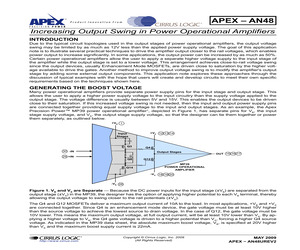
1N5350B +VB1 OUT -VB1 OUT R7 15K L1 D1 1N4148 2 R2 6 249K 7 C13 1000pF C9 1F 3 TLC555 TIMER C8 0.01F T2 D7 R8 R9 MUR120 1.0 C7 1.0 C11 4.7F 4.7F + C3 47F +VB2 OUT D4 1N5350B -VB2 OUT X1 8 4 5 R11 301 D5 1N4739A D2 1N4148 -VS IN R10 R1 MUR120 1.0 R4 301 M1 IRF620PBF (HEATSINK REQUIRED) 1 C1 330pF R3 1.0 Figure 3. A Low-Cost DC-to-DC Converter -- This converter can be employed to supply the boost voltages (+VB and -VB) necessary to increase the output swing. AN48U AN48 P r o d u c t I n n o v a t i o nF r o m Table 1. Parts List for DC to DC Converter Circuit Shown in Figure 3 REFERENCE DESIGNATION DESCRIPTION PART NUMBER (DIGI-KEY) C11, C12,C6,C7 CAPACITOR, X7R CERAMIC, 4.7F, 25V, TDK 445-2886-ND C1 CAPACITOR, COG CERAMIC, 330pF, 50V, MURATA 490-3724-ND C2, C3 CAPACITOR, TANTALUM, 47F, 25V, AVX, TAP476K025CCS 478-4181-ND C8 CAPACITOR, X7R CERAMIC, 0.01F, 100V, MURATA 490-3813-ND C9 CAPACITOR, X7R CERAMIC, 1.0F, 50V, TDK 445-2884-ND C10 CAPACITOR, POLY FILM, 4.7F, 250V, PANASONIC EF2475-ND C13 CAPA
 10 Pages, 622 KB, Original
IRF620PBF * Lead-Free 1 IRF620PBF 2 IRF620PBF TO-220AB Package Outline Dimensions are shown in millimeters (inches) 10.54 (.415) 10.29 (.405) 2.87 (.113) 2.62 (.103) -B- 3.78 (.149) 3.54 (.139) 4.69 (.185) 4.20 (.165) -A- 1.32 (.052) 1.22 (.048) 6.47 (.255) 6.10 (.240) 4 15.24 (.600) 14.84 (.584) LEAD ASSIGNMENTS 1.15 (.045) MIN 1 2 3 4- DRAIN 14.09 (.555) 13.47 (.530) 4- COLLECTOR 4.06 (.160) 3.55 (.140) 3X 3X LEAD ASSIGNMENTS IGBTs, CoPACK 1 - GATE 2 - DRAIN 1- GATE 1- GATE 3 - SOURCE 2- COLLECTOR 2- DRAIN 3- SOURCE 3- EMITTER 4 - DRAIN HEXFET 1.40 (.055) 1.15 (.045) 0.93 (.037) 0.69 (.027) 0.36 (.014) 3X M B A M 0.55 (.022) 0.46 (.018) 2.92 (.115) 2.64 (.104) 2.54 (.100) 2X NOTES: 1 DIMENSIONING & TOLERANCING PER ANSI Y14.5M, 1982. 2 CONTROLLING DIMENSION : INCH 3 OUTLINE CONFORMS TO JEDEC OUTLINE TO-220AB. 4 HEATSINK & LEAD MEASUREMENTS DO NOT INCLUDE BURRS. TO-220AB Part Marking Information E XAMPL E : T HIS IS AN IR F 1010 L OT CODE 1789 AS S E MB L E D ON WW 19, 1
 3 Pages, 376 KB, Original
 C2 47F D3 1N5350B +VB1 OUT -VB1 OUT R7 15K L1 2 R2 6 249K 7 C13 1000pF C9 1F 3 TLC555 TIMER C8 0.01F T2 D7 R8 R9 MUR120 1.0 C7 1.0 C11 4.7F 4.7F + C3 47F +VB2 OUT D4 1N5350B -VB2 OUT X1 8 4 5 R11 301 D5 1N4739A D2 1N4148 D1 1N4148 -VS IN R10 R1 R4 301 M1 IRF620PBF (HEATSINK REQUIRED) 1 C1 330pF R3 1.0 Figure 3. A Low-Cost DC-to-DC Converter -- This converter can be employed to supply the boost voltages (+VB and -VB) necessary to increase the output swing. AN48U 3 AN48 Table 1. Parts List for DC to DC Converter Circuit Shown in Figure 3 4 REFERENCE DESIGNATION DESCRIPTION PART NUMBER (DIGI-KEY) C11, C12,C6,C7 CAPACITOR, X7R CERAMIC, 4.7F, 25V, TDK 445-2886-ND C1 CAPACITOR, COG CERAMIC, 330pF, 50V, MURATA 490-3724-ND C2, C3 CAPACITOR, TANTALUM, 47F, 25V, AVX, TAP476K025CCS 478-4181-ND C8 CAPACITOR, X7R CERAMIC, 0.01F, 100V, MURATA 490-3813-ND C9 CAPACITOR, X7R CERAMIC, 1.0F, 50V, TDK 445-2884-ND C10 CAPACITOR, POLY FILM, 4.7F, 250V, PANASONIC EF2475-ND C13 CAPACITOR, X7R CERAMIC, 1000pF, 200V, KEM
 10 Pages, 493 KB, Original
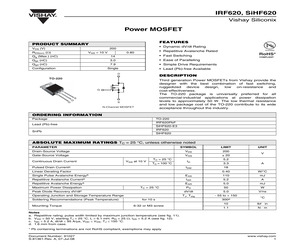
d low package cost of the TO-220AB contribute to its wide acceptance throughout the industry. G D COMPLIANT * Compliant to RoHS Directive 2002/95/EC D G Available * Repetitive Avalanche Rated 0.80 S S N-Channel MOSFET ORDERING INFORMATION Package TO-220AB IRF620PBF SiHF620-E3 IRF620 SiHF620 Lead (Pb)-free SnPb ABSOLUTE MAXIMUM RATINGS (TC = 25 C, unless otherwise noted) PARAMETER SYMBOL LIMIT Drain-Source Voltage VDS 200 Gate-Source Voltage VGS 20 Continuous Drain Current VGS at 10 V TC = 25 C TC = 100 C Pulsed Drain Currenta ID IDM Linear Derating Factor UNIT V 5.2 3.3 A 18 0.40 W/C Single Pulse Avalanche Energyb EAS 110 mJ Repetitive Avalanche Currenta IAR 5.2 A Repetitive Avalanche Energya EAR 5.0 mJ Maximum Power Dissipation TC = 25 C Peak Diode Recovery dV/dtc Operating Junction and Storage Temperature Range Soldering Recommendations (Peak Temperature) Mounting Torque for 10 s 6-32 or M3 screw PD 50 W dV/dt 5.0 V/ns TJ, Tstg - 55 to + 150 300d C 10 lbf * in 1.1 N*m Notes a. Repetitive rating
 10 Pages, 281 KB, Original
-IRF530SPBF 844-IRFI540GPBF 844-IRF540PBF 844-IRF540SPBF 844-IRFP140PBF 844-IRFP150PBF 844-FB180SA10P 844-IRFD210PBF 844-IRFD220PBF 844-IRFL210PBF 844-IRFR210PBF 844-IRFU210PBF 844-IRF610PBF 844-IRF610SPBF 844-IRFI620GPBF 844-IRFR220PBF 844-IRFU220PBF 844-IRF620PBF 844-IRF620SPBF 844-IRFI630GPBF 844-IRF630PBF 844-IRF630SPBF (c) Copyright 2011 Mouser Electronics 504 Vishay Part No. Package VDS (Max)(V) ID (Max)(A) IDM (Max)(A) RDS(on) Max () @ VGS=10V PD (Max)(W) IRFD010PBF HD-1 50 1.7 - - - - - - - - - - IRFD020PBF HD-1 50 2.4 - - - - - 0.100 IRFU020PBF TO-251AA 50 15 - - - - - - - - - - IRFZ20PBF TO-220AB 50 17 - - - - - 0.100 IRFZ30PBF TO-220AB 50 30 - - - - - 0.050 IRFZ40PBF TO-220AB 50 50 - - - - - - - - - - IRFD014PBF HD-1 601.714 0.200 IRFD024PBF HD-1 602.520 0.100 IRFL014PBF SOT-223 602.722 0.200 IRLR014PBF TO-252AA 60 7.7 31 0.200 @ 5V IRFR014PBF TO-252AA 607.731 0.200 IRFU014PBF TO-251AA 607.731 0.200 IRFIZ14GPBF TO-220 FullPAK 60 8.0 32 0.200 IRLZ14SPBF TO-252AA 60 10 40 0.200 @ 5V IRFZ
 379 Pages, 47721 KB, Original
BF IRF820APBF 10 36 115 ST 5.2 4.8 20.8 19.2 125 140 ST STP7NK80Z FCH FQP5N80 Mftrs. Mftr. List No. IRFB260NPBF IRFB38N20DPBF IRFB42N20DPBF IRFB31N20DPBF IRFB23N20DPBF FQP19N20 BUZ30A IRF640NPBF IRFB17N20DPBF IRF640PBF BUZ31 IRF630NPBF BUZ73 IRF630 BUZ73A IRF620PBF IRF620 IRF610PBF 2 STP10NK60Z 211275 Price Each Mftrs. List No. Mftr. Order Code 1+ 25+ 100+ BUZ30A BUZ31 BUZ73 BUZ73A FDP3652 FQP5N80 FQP19N20 IRF510PBF IRF520PBF IRF610PBF IRF710PBF IRF720PBF IRF730PBF IRF740PBF IRF820PBF INF INF INF INF FCH FCH FCH VISH VISH VISH VISH VISH VISH VISH VISH 105-6528 105-6531 115-6440 115-6438 101-7692 984-5623 984-5500 864-8204 864-8239 864-8328 864-8417 864-8425 864-8441 864-8484 864-8514 IRF830PBF IRF840PBF IRF1310NPBF IRF3315PBF IRF3415PBF IRF3710PBF IRF3710ZPBF IRF3711PBF IRF540ZPBF VISH VISH IR IR IR IR IR IR IR 864-8549 864-8581 910-3023 864-8077 864-8093 864-8166 101-3470 864-8182 821-0667 IRF520NPBF IRF520VPBF IR IR 910-3031 865-7688 2.24 1.74 1.24 1.53 1.86 1.70 1.20 1.18 1.74 1.88 1.27 2.54 1
 144 Pages, 26045 KB, Original
PBF IRF510PBF IRF510SPBF IRFI520GPBF IRFR120PBF IRFU120PBF IRF520PBF IRFI530GPBF IRF530PBF IRF530SPBF IRFI540GPBF IRF540PBF IRF540SPBF IRFP140PBF IRFP150PBF IRFD210PBF IRFD220PBF IRFR210PBF IRFU210PBF IRF610PBF IRF610SPBF IRFI620GPBF IRFR220PBF IRFU220PBF IRF620PBF IRF620SPBF IRFI630GPBF IRF630PBF IRF630SPBF IRFI640GPBF IRF640PBF IRF640SPBF IRFP240PBF IRFP250PBF IRFP260PBF IRFD224PBF IRFI614GPBF IRFR214PBF IRFU214PBF IRFR224PBF IRFU224PBF IRF624PBF IRF624SPBF IRFI634GPBF IRFI644GPBF IRF634PBF IRF644PBF IRF644SPBF IRFP244PBF IRFP254PBF IRFP264PBF IRFD310PBF IRFD420PBF IRFD320PBF IRFR310PBF IRFU310PBF IRF710PBF IRF710SPBF IRFI720GPBF IRFR320PBF IRFU320PBF IRF720PBF IRF720SPBF IRFI730GPBF IRFI740GPBF IRF730PBF IRF730APBF IRF730ASPBF IRF740PBF IRF740ASPBF IRF740SPBF IRF740APBF IRF740ALPBF IRFP340PBF IRFP350PBF Package TO-220AB TO-220AB TO-220AB TO-263 TO-220AB TO-247AC TO-247AC TO-247AC HD-1 HD-1 HD-1 TO-252AA TO-251AA TO-220FP TO-220AB TO-252AA TO-220FP TO-252AA TO-251AA TO-220AB TO-220FP TO-220AB T
 1 Pages, 240 KB, Original
IRFB52N15DPBF IRFB61N15DPBF IRFS4228TRLPBF IRFB4321GPBF IRFSL4115PBF IRFS4115PBF IRFS4115TRLPBF IRFB4115PBF IRFB4115GPBF IRFS4115-7PPBF IRFS4115TRL7PP IRFPS3815PBF IRFP4568PBF IRF7464PBF IRF7450PBF IRFU210PBF IRFR220NTRPBF IRFR220NPBF IRL620PBF IRL620SPBF IRF620PBF IRLI630GPBF IRL630PBF IRF630NSTRLPBF IRF630NPBF IRF630NSPBF IRFR9N20DPBF IRFI640GPBF IRLI640GPBF IRFR13N20DPBF IRFU13N20DPBF IRFS17N20DPBF IRFS17N20DTRLP IRL640PBF IRL640SPBF IRFS4020PBF IRF640NSTRLPBF IRF640NSTRRPBF IRF640NLPBF IRF640NSPBF IRF640PBF IRFP240PBF IRFSL5620PBF IRFS4620PBF IRFS5620PBF IRFS5620TRLPBF IRFS4620TRLPBF IRFR4620TRLPBF IRFB23N20DPBF IRFS23N20DPBF IRFS23N20DTRLP IRFB5620PBF V(BR) ID (A) R DS(ON) (V) @ 25C () 150 33 56 150 33 56 150 33 34 150 33 34 150 33 34 150 33 34.5 150 33 34.5 150 33 34.5 150 33 34.5 150 33 34.5 150 33 34.5 150 33 56 150 35 32 150 41 45 150 41 45 150 41 45 150 41 45 150 43 42 150 43 42 150 43 42 150 43 42 150 60 32 150 60 32 150 60 32 150 83 12 150 83 15 150 99 10.3 150 99 10.3 150 99 10.3 150
 375 Pages, 58008 KB, Original
d low package cost of the TO-220AB contribute to its wide acceptance throughout the industry. G D COMPLIANT * Compliant to RoHS Directive 2002/95/EC D G Available * Repetitive Avalanche Rated 0.80 S S N-Channel MOSFET ORDERING INFORMATION Package TO-220AB IRF620PBF SiHF620-E3 IRF620 SiHF620 Lead (Pb)-free SnPb ABSOLUTE MAXIMUM RATINGS (TC = 25 C, unless otherwise noted) PARAMETER SYMBOL LIMIT Drain-Source Voltage VDS 200 Gate-Source Voltage VGS 20 Continuous Drain Current VGS at 10 V TC = 25 C TC = 100 C Pulsed Drain Currenta ID IDM Linear Derating Factor UNIT V 5.2 3.3 A 18 0.40 W/C Single Pulse Avalanche Energyb EAS 110 mJ Repetitive Avalanche Currenta IAR 5.2 A Repetitive Avalanche Energya EAR 5.0 mJ Maximum Power Dissipation TC = 25 C Peak Diode Recovery dV/dtc Operating Junction and Storage Temperature Range Soldering Recommendations (Peak Temperature) Mounting Torque for 10 s 6-32 or M3 screw PD 50 W dV/dt 5.0 V/ns TJ, Tstg - 55 to + 150 300d C 10 lbf * in 1.1 N*m Notes a. Repetitive rating
 9 Pages, 205 KB, Original
 thermal resistance and low package cost of the TO-220 contribute to its wide acceptance throughout the industry. G S D RoHS* * Lead (Pb)-free Available D G Available * Repetitive Avalanche Rated 0.80 S N-Channel MOSFET ORDERING INFORMATION Package TO-220 IRF620PBF SiHF620-E3 IRF620 SiHF620 Lead (Pb)-free SnPb ABSOLUTE MAXIMUM RATINGS TC = 25 C, unless otherwise noted PARAMETER SYMBOL LIMIT Drain-Source Voltage VDS 200 Gate-Source Voltage VGS 20 Continuous Drain Current VGS at 10 V TC = 25 C TC = 100 C Pulsed Drain Currenta ID IDM Linear Derating Factor UNIT V 5.2 3.3 A 18 0.40 W/C Single Pulse Avalanche Energyb EAS 110 mJ Repetitive Avalanche Currenta IAR 5.2 A EAR 5.0 mJ PD 50 W dV/dt 5.0 V/ns TJ, Tstg - 55 to + 150 Repetitive Avalanche Energya Maximum Power Dissipation TC = 25 C Peak Diode Recovery dV/dtc Operating Junction and Storage Temperature Range Soldering Recommendations (Peak Temperature) Mounting Torque for 10 s 6-32 or M3 screw 300d C 10 lbf * in 1.1 N*m Notes a. Repetitive rating;
 8 Pages, 1591 KB, Original
d low package cost of the TO-220AB contribute to its wide acceptance throughout the industry. G D COMPLIANT * Compliant to RoHS Directive 2002/95/EC D G Available * Repetitive Avalanche Rated 0.80 S S N-Channel MOSFET ORDERING INFORMATION Package TO-220AB IRF620PBF SiHF620-E3 IRF620 SiHF620 Lead (Pb)-free SnPb ABSOLUTE MAXIMUM RATINGS (TC = 25 C, unless otherwise noted) PARAMETER SYMBOL LIMIT Drain-Source Voltage VDS 200 Gate-Source Voltage VGS 20 Continuous Drain Current VGS at 10 V TC = 25 C TC = 100 C Pulsed Drain Currenta ID IDM Linear Derating Factor UNIT V 5.2 3.3 A 18 0.40 W/C Single Pulse Avalanche Energyb EAS 110 mJ Repetitive Avalanche Currenta IAR 5.2 A Repetitive Avalanche Energya EAR 5.0 mJ Maximum Power Dissipation TC = 25 C Peak Diode Recovery dV/dtc Operating Junction and Storage Temperature Range Soldering Recommendations (Peak Temperature) Mounting Torque for 10 s 6-32 or M3 screw PD 50 W dV/dt 5.0 V/ns TJ, Tstg - 55 to + 150 300d C 10 lbf * in 1.1 N*m Notes a. Repetitive rating
 9 Pages, 280 KB, Original
d low package cost of the TO-220AB contribute to its wide acceptance throughout the industry. G D COMPLIANT * Compliant to RoHS Directive 2002/95/EC D G Available * Repetitive Avalanche Rated 0.80 S S N-Channel MOSFET ORDERING INFORMATION Package TO-220AB IRF620PBF SiHF620-E3 IRF620 SiHF620 Lead (Pb)-free SnPb ABSOLUTE MAXIMUM RATINGS (TC = 25 C, unless otherwise noted) PARAMETER SYMBOL LIMIT Drain-Source Voltage VDS 200 Gate-Source Voltage VGS 20 Continuous Drain Current VGS at 10 V TC = 25 C TC = 100 C Pulsed Drain Currenta ID IDM Linear Derating Factor UNIT V 5.2 3.3 A 18 0.40 W/C Single Pulse Avalanche Energyb EAS 110 mJ Repetitive Avalanche Currenta IAR 5.2 A Repetitive Avalanche Energya EAR 5.0 mJ Maximum Power Dissipation TC = 25 C Peak Diode Recovery dV/dtc Operating Junction and Storage Temperature Range Soldering Recommendations (Peak Temperature) Mounting Torque for 10 s 6-32 or M3 screw PD 50 W dV/dt 5.0 V/ns TJ, Tstg - 55 to + 150 300d C 10 lbf * in 1.1 N*m Notes a. Repetitive rating
 8 Pages, 135 KB, Original
d low package cost of the TO-220AB contribute to its wide acceptance throughout the industry. G D COMPLIANT * Compliant to RoHS Directive 2002/95/EC D G Available * Repetitive Avalanche Rated 0.80 S S N-Channel MOSFET ORDERING INFORMATION Package TO-220AB IRF620PBF SiHF620-E3 IRF620 SiHF620 Lead (Pb)-free SnPb ABSOLUTE MAXIMUM RATINGS (TC = 25 C, unless otherwise noted) PARAMETER SYMBOL LIMIT Drain-Source Voltage VDS 200 Gate-Source Voltage VGS 20 Continuous Drain Current VGS at 10 V TC = 25 C TC = 100 C Pulsed Drain Currenta ID IDM Linear Derating Factor UNIT V 5.2 3.3 A 18 0.40 W/C Single Pulse Avalanche Energyb EAS 110 mJ Repetitive Avalanche Currenta IAR 5.2 A Repetitive Avalanche Energya EAR 5.0 mJ Maximum Power Dissipation TC = 25 C Peak Diode Recovery dV/dtc Operating Junction and Storage Temperature Range Soldering Recommendations (Peak Temperature) Mounting Torque for 10 s 6-32 or M3 screw PD 50 W dV/dt 5.0 V/ns TJ, Tstg - 55 to + 150 300d C 10 lbf * in 1.1 N*m Notes a. Repetitive rating
 9 Pages, 205 KB, Original


