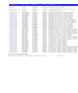
in Linear Technology LTC490IS8 SP490EN Full Duplex, 5Mbps, RS-485 Driver and Receiver 8 NSOIC Pin to Pin Linear Technology LTC491CN SP491CP Full Duplex, 5Mbps, RS-485 Driver and Receiver, Driver and Receiver, Tri-state 14 PDIP Pin to Pin Linear Technology LTC491CS SP491CN Full Duplex, 5Mbps, RS-485 Driver and Receiver, Driver and Receiver, Tri-state 14 NSOIC Pin to Pin Linear Technology LTC491IN SP491EP Full Duplex, 5Mbps, RS-485 Driver and Receiver, Driver and Receiver, Tri-state 14 PDIP Pin to Pin Linear Technology LTC491IS SP491EN Full Duplex, 5Mbps, RS-485 Driver and Receiver, Driver and Receiver, Tri-state 14 NSOIC Pin to Pin Sipex Cross Reference Page 21 Competitor Comp P/N Sipex P/N Description Package Cross type Linear Technology LTC660CN8 SP6660CP 3V Charge Pump DC to DC Converter 8 PDIP Pin to Pin Linear Technology LTC660CS8 SP6660CN 3V Charge Pump DC to DC Converter 8 NSOIC Pin to Pin Linear Technology LTC690CN8 SP690ACP Low Power Microprocessor Supervisory With Battery Switch-Over 8 P
 115 Pages, 1473 KB, Original
AIS8-ND LT2178CS8-ND LT2178IS8-ND LT2179ACS-ND -- -- -- -- -- -- -- -- -- -- -- -- -- -- -- LTC485CN8-ND LTC485CS8-ND LTC486CN-ND LTC486CSW-ND LTC487CN-ND LTC487CSW-ND LTC488CN-ND LTC488CSW-ND LTC489CN-ND LTC489CSW-ND LTC490CN8-ND LTC490CS8-ND LTC491CN-ND LTC491CS-ND LTC660CN8-ND LTC660CS8-ND LTC690CN8-ND LTC690CS8-ND LTC691CN-ND 9176B-ND 9176B-ND 9176B-ND 9176B-ND 9176B-ND 9176B-ND 9210B-ND 9210B-ND 9210B-ND 9210B-ND 9176B-ND 9176B-ND 9176B-ND 9176B-ND 9257B-ND 9257B-ND 9176B-ND 9176B-ND 9176B-ND 9176B-ND 8.13 125.00 435.00 7.50 115.00 400.00 7.88 121.25 420.00 LTC691CSW-ND LTC692CN8-ND LTC692CS8-ND LTC693CN-ND LTC693CSW-ND LTC694CN8-ND LTC694CN8-3.3-ND LTC694CS8-ND LTC694CS8-3.3-ND LTC695CN-ND 9210B-ND 9210B-ND 9210B-ND 9210B-ND 9176B-ND 9210B-ND 9210B-ND 9210B-ND 9176B-ND LTC695CN-3.3-ND 9210B-ND 6.00 92.50 320.00 6.88 4.13 106.25 68.75 365.00 250.00 4.13 68.75 250.00 4.13 68.75 250.00 4.13 68.75 250.00 3.88 63.75 225.00 3.88 63.75 225.00 3.88 6.50 63.75 108.75 225.00 375.00 6.50 108.75 370.00
 531 Pages, 19076 KB, Original
F LTC1482CS8#PBF LTC1484CS8#PBF LTC1487CN8#PBF LTC1487CS8#PBF LTC1535CSW#PBF LTC1535ISW#PBF LTC1685CS8#PBF LTC1686CS8#PBF LTC1686IS8#PBF LTC2852IMS#PBF LTC2856CMS8-2#PBF LTC2857CMS8-1#PBF LTC486CSW#PBF LTC487CSW#PBF LTC488CN#PBF LTC489CSW#PBF LTC491CN#PBF LTC491CS#PBF LTC491IS#PBF LTC1485CS8#PBF LTC1485IS8#PBF LTC1690CS8#PBF LTC2850HMS8#PBF LTC2850IS8#PBF LTC2851IDD#PBF LTC2851IS8#PBF LTC2852CS#PBF LTC2854CDD#PBF LTC2854HDD#PBF LTC2856HMS8-2#PBF LTC2857HMS8-2#PBF LTC2859CDD#PBF LTC2859IDD#PBF # of DRVRs 1 1 1 1 1 1 1 1 1 1 1 1 1 1 1 1 4 4 1 1 1 1 1 1 1 1 1 1 1 1 1 1 1 1 1 1 1 # of RCVRs 1 1 1 1 1 1 1 1 1 1 1 1 1 1 1 1 1 1 4 4 1 1 1 1 1 1 1 1 1 1 1 1 1 1 1 1 1 Package 8-DIP 8-SOIC 8-SOIC 8-SO 8-SOIC 8-SO 8-DIP 8-SO 28-SOIC 28-SO 8-SOIC 8-SOIC 8-SOIC 10-MSOP 8-MSOP 8-MSOP 16-SOL 16-SOL 16-DIP 16-SOL 14-DIP 14-SO 14-SO 8-SO 8-SO 8-SOIC 8-MSOP 8-SOIC 8-DFN 8-SOIC 14-SOIC 10-DFN 10-DFN 8-MSOP 8-MSOP 10-DFN 10-DFN Stock No. 56M9601 56M9603 56M1547 56M1553 56M1575 56M1603 56M1625 56M1627 56M1821 56M1825
 375 Pages, 58008 KB, Original
LTC491CS except that the Operating Temperature range is - 40C to 85C. For complete specifications, typical performance curves and applications information, please see the LTC491 data sheet. For further information regarding this specification notice contact: Linear Technology Corporation 1630 McCarthy Blvd. Milpitas, California 95035-7487 Attn: Product Marketing Manager Phone: (408) 432-1900 (c)1994 LT/GP 0894 * PRINTED IN USA
 1 Pages, 47 KB, Original
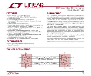
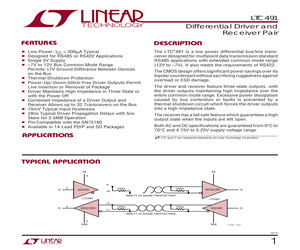
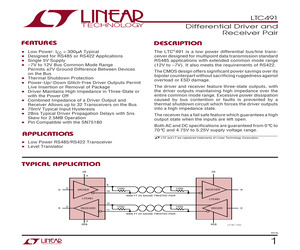
ge ................. - 65C to 150C Lead Temperature (Soldering, 10 sec).................. 300C U AXI U W (Note 1) U ABSOLUTE PACKAGE/ORDER I FOR ATIO ORDER PART NUMBER TOP VIEW NC 1 14 VCC R 13 NC R 2 REB 3 12 A DE 4 11 B D 5 GND 6 9 Y GND 7 8 NC LTC491CN LTC491CS LTC491IN LTC491IS 10 Z D N PACKAGE 14-LEAD PDIP S PACKAGE 14-LEAD PLASTIC SO TJMAX = 100C, JA = 90C/W (N) TJMAX = 100C, JA = 110C/W (S) Consult LTC Marketing for parts specified with wider operating temperature ranges. DC ELECTRICAL CHARACTERISTICS The denotes the specifications which apply over the full operating temperature range, otherwise specifications are at TA = 25C. VCC = 5V 5% SYMBOL PARAMETER CONDITIONS MIN VOD1 Differential Driver Output Voltage (Unloaded) IO = 0 VOD2 Differential Driver Output Voltage (With load) R = 50; (RS422) 2 R = 27; (RS485) (Figure 1) 1.5 R = 27 or R = 50 (Figure 1) TYP MAX 5 UNITS V V 5 V 0.2 V VOD Change in Magnitude of Driver Differential Output Voltage for Complementary Output States VOC Driver Com
 12 Pages, 161 KB, Original
ge ................. - 65C to 150C Lead Temperature (Soldering, 10 sec).................. 300C U AXI U W (Note 1) U ABSOLUTE PACKAGE/ORDER I FOR ATIO ORDER PART NUMBER TOP VIEW NC 1 14 VCC R 13 NC R 2 REB 3 12 A DE 4 11 B D 5 GND 6 9 Y GND 7 8 NC LTC491CN LTC491CS LTC491IN LTC491IS 10 Z D N PACKAGE 14-LEAD PDIP S PACKAGE 14-LEAD PLASTIC SO TJMAX = 100C, JA = 90C/W (N) TJMAX = 100C, JA = 110C/W (S) Consult LTC Marketing for parts specified with wider operating temperature ranges. DC ELECTRICAL CHARACTERISTICS The denotes the specifications which apply over the full operating temperature range, otherwise specifications are at TA = 25C. VCC = 5V 5% SYMBOL PARAMETER CONDITIONS MIN VOD1 Differential Driver Output Voltage (Unloaded) IO = 0 VOD2 Differential Driver Output Voltage (With load) R = 50; (RS422) 2 R = 27; (RS485) (Figure 1) 1.5 R = 27 or R = 50 (Figure 1) TYP MAX 5 UNITS V V 5 V 0.2 V VOD Change in Magnitude of Driver Differential Output Voltage for Complementary Output States VOC Driver Com
 12 Pages, 178 KB, Original
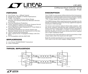
ge ................. - 65C to 150C Lead Temperature (Soldering, 10 sec.)................. 300C U AXI U W (Note 1) U ABSOLUTE PACKAGE/ORDER I FOR ATIO TOP VIEW NC 1 R 2 REB 3 12 A DE 4 11 B D 5 GND 6 9 Y GND 7 8 NC ORDER PART NUMBER 14 VCC R 13 NC LTC491CN LTC491CS LTC491IN LTC491IS 10 Z D S PACKAGE N PACKAGE 14-LEAD PLASTIC DIP 14-LEAD PLASTIC SOIC LTC491 * POI01 Consult factory for Military grade parts. DC ELECTRICAL CHARACTERISTICS VCC = 5V 5% SYMBOL PARAMETER CONDITIONS MIN VOD1 Differential Driver Output Voltage (Unloaded) IO = 0 VOD2 Differential Driver Output Voltage (With load) R = 50; (RS422) 2 R = 27; (RS485) (Figure 1) 1.5 5 V VOD Change in Magnitude of Driver Differential Output Voltage for Complementary Output States R = 27 or R = 50 (Figure 1) 0.2 V VOC Driver Common Mode Output Voltage 3 V VOC Change in Magnitude of Driver Common Mode Output Voltage for Complementary Output States 0.2 V VIH Input High Voltage VIL Input Low Voltage 0.8 V lIN1 Input Current 2 A lIN2 Input Current (A,
 12 Pages, 169 KB, Original
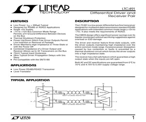
ge ................. - 65C to 150C Lead Temperature (Soldering, 10 sec.)................. 300C U AXI U W (Note 1) U ABSOLUTE PACKAGE/ORDER I FOR ATIO TOP VIEW NC 1 R 2 REB 3 12 A DE 4 11 B D 5 GND 6 9 Y GND 7 8 NC ORDER PART NUMBER 14 VCC R 13 NC LTC491CN LTC491CS LTC491IN LTC491IS 10 Z D S PACKAGE N PACKAGE 14-LEAD PLASTIC DIP 14-LEAD PLASTIC SOIC LTC491 * POI01 Consult factory for Military grade parts. DC ELECTRICAL CHARACTERISTICS VCC = 5V 5% SYMBOL PARAMETER CONDITIONS VOD1 Differential Driver Output Voltage (Unloaded) IO = 0 MIN VOD2 Differential Driver Output Voltage (With load) R = 50; (RS422) 2 R = 27; (RS485) (Figure 1) 1.5 5 V VOD Change in Magnitude of Driver Differential Output Voltage for Complementary Output States R = 27 or R = 50 (Figure 1) 0.2 V VOC Driver Common Mode Output Voltage 3 V VOC Change in Magnitude of Driver Common Mode Output Voltage for Complementary Output States 0.2 V VIH Input High Voltage VIL Input Low Voltage 0.8 V lIN1 Input Current 2 A lIN2 Input Current (A,
 12 Pages, 194 KB, Original
in Linear Technology LTC490IS8 SP490EN Full Duplex, 5Mbps, RS-485 Driver and Receiver 8 NSOIC Pin to Pin Linear Technology LTC491CN SP491CP Full Duplex, 5Mbps, RS-485 Driver and Receiver, Driver and Receiver, Tri-state 14 PDIP Pin to Pin Linear Technology LTC491CS SP491CN Full Duplex, 5Mbps, RS-485 Driver and Receiver, Driver and Receiver, Tri-state 14 NSOIC Pin to Pin Linear Technology LTC491IN SP491EP Full Duplex, 5Mbps, RS-485 Driver and Receiver, Driver and Receiver, Tri-state 14 PDIP Pin to Pin Linear Technology LTC491IS SP491EN Full Duplex, 5Mbps, RS-485 Driver and Receiver, Driver and Receiver, Tri-state 14 NSOIC Pin to Pin Sipex Cross Reference Page 21 Competitor Comp P/N Sipex P/N Description Package Cross type Linear Technology LTC660CN8 SP6660CP 3V Charge Pump DC to DC Converter 8 PDIP Pin to Pin Linear Technology LTC660CS8 SP6660CN 3V Charge Pump DC to DC Converter 8 NSOIC Pin to Pin Linear Technology LTC690CN8 SP690ACP Low Power Microprocessor Supervisory With Battery Switch-Over 8 P
 55 Pages, 359 KB, Original
 Interface Full Duplex, 5Mbps, RS-485 Pin Driver and Receiver 8 Pin NSOIC Pin to Pin Linear Technology LTC491CN ZT491LEEP Interface Full Duplex, 5Mbps, RS-485 Pin Driver and Receiver, Driver and Receiver, Tri-state 14 Pin PDIP Pin to Pin Linear Technology LTC491CS ZT491LEEN Interface Full Duplex, 5Mbps, RS-485 Pin Driver and Receiver, Driver and Receiver, Tri-state 14 Pin NSOIC Pin to Pin Linear Technology LTC491IS ZT491LEEN Interface Full Duplex, 5Mbps, RS-485 Pin Driver and Receiver, Driver and Receiver, Tri-state 14 Pin NSOIC Pin to Pin Macroblock MBI1008 ZD3315LED LED drive Inductorless four channel constant current LED driver 8 DFN 2x3 Pin to Pin Macroblock MBI6001N1D ZD831LEY LED drive Transformerless AC/DC constant current LED driver 20 EX-TSSOP Macroblock MBI6001N1N ZD831LEY LED drive Transformerless AC/DC constant current LED driver 20 EX-TSSOP Macroblock MBI6001N2D ZD831LEY LED drive Transformerless AC/DC constant current LED driver 20 EX-TSSOP Macroblock MBI6001N2N ZD831LEY LED drive T
 18 Pages, 45 KB, Original
ge ................. - 65C to 150C Lead Temperature (Soldering, 10 sec).................. 300C U AXI U W (Note 1) U ABSOLUTE PACKAGE/ORDER I FOR ATIO ORDER PART NUMBER TOP VIEW NC 1 14 VCC R 13 NC R 2 REB 3 12 A DE 4 11 B D 5 GND 6 9 Y GND 7 8 NC LTC491CN LTC491CS LTC491IN LTC491IS 10 Z D N PACKAGE 14-LEAD PDIP S PACKAGE 14-LEAD PLASTIC SO TJMAX = 100C, JA = 90C/W (N) TJMAX = 100C, JA = 110C/W (S) Consult LTC Marketing for parts specified with wider operating temperature ranges. DC ELECTRICAL CHARACTERISTICS The denotes the specifications which apply over the full operating temperature range, otherwise specifications are at TA = 25C. VCC = 5V 5% SYMBOL PARAMETER CONDITIONS MIN VOD1 Differential Driver Output Voltage (Unloaded) IO = 0 VOD2 Differential Driver Output Voltage (With load) R = 50; (RS422) 2 R = 27; (RS485) (Figure 1) 1.5 R = 27 or R = 50 (Figure 1) TYP MAX 5 UNITS V V 5 V 0.2 V VOD Change in Magnitude of Driver Differential Output Voltage for Complementary Output States VOC Driver Com
 12 Pages, 175 KB, Original
ge ................. - 65C to 150C Lead Temperature (Soldering, 10 sec.)................. 300C U AXI U W (Note 1) U ABSOLUTE PACKAGE/ORDER I FOR ATIO TOP VIEW NC 1 R 2 REB 3 12 A DE 4 11 B D 5 GND 6 9 Y GND 7 8 NC ORDER PART NUMBER 14 VCC R 13 NC LTC491CN LTC491CS LTC491IN LTC491IS 10 Z D S PACKAGE N PACKAGE 14-LEAD PLASTIC DIP 14-LEAD PLASTIC SOIC LTC491 * POI01 Consult factory for Military grade parts. DC ELECTRICAL CHARACTERISTICS VCC = 5V 5% SYMBOL PARAMETER CONDITIONS VOD1 Differential Driver Output Voltage (Unloaded) IO = 0 MIN VOD2 Differential Driver Output Voltage (With load) R = 50; (RS422) 2 R = 27; (RS485) (Figure 1) 1.5 5 V VOD Change in Magnitude of Driver Differential Output Voltage for Complementary Output States R = 27 or R = 50 (Figure 1) 0.2 V VOC Driver Common Mode Output Voltage 3 V VOC Change in Magnitude of Driver Common Mode Output Voltage for Complementary Output States 0.2 V VIH Input High Voltage VIL Input Low Voltage 0.8 V lIN1 Input Current 2 A lIN2 Input Current (A,
 40 Pages, 564 KB, Original


