NLCV32T-4R7M-PFR Applications Commercial Grade No Directivity No Directivity Feature Wire Wound Wire Wound Ferrite Core Ferrite Core Series | Type NLCV32-PFR Production (Not Recommended for New Design) Status Recommended Alternate Part No. : NLCV32T-4R7M-EFR (Interchangeability is not guaranteed.) Brand TDK Size Length(L) 3.20mm 0.20mm Width(W) 2.50mm 0.20mm Thickness | Height 2.20mm 0.20mm Recommended Land Pattern (A) 1.20mm Nom. Recommended Land Pattern (B) 2.00mm Nom. Recommended Land Pattern (C) 2.00mm Nom. Electrical Characteristics Inductance 4.7H 20% at 7.96MHz Rated Current 900mA DC Resistance [Typ.] 200m DC Resistance [Max.] 240m Self Resonant Frequency [Min.] 46MHz Self Resonant Frequency [Typ.] Q [Min.] Q [Typ.] 15 Other Operating Temp. Range (Including Self-Temp. Rise) -40 to 125C Wave (Flow) Soldering Method Reflow Iron Soldering AEC-Q200 No Packing Blister (Plastic)Taping [180mm Reel] Package Quantity 2000pcs Weight 0.05g ! Images are for reference only and show exemplary products.
 4 Pages, 230 KB, Original
ent from Li-Ion battery source. Series LEDs L 22H 3 10H 4.7H 22H 4 10H 4.7H 22H 5,6 10H 4.7H June 2007 Manufacturer Min COUT LQH43MN220K03 (Murata) 2.2F NLC453232T-220K (TDK) LQH43MN100K03 (Murata) 0.33F NLCV32T-100K-PFR (TDK) LQH43MN4R7K03 (Murata) 0.22F NLCV32T-4R7M-PFR (TDK) LQH43MN220K03 (Murata) 1.0F NLC453232T-220K (TDK) LQH43MN100K03 (Murata) 0.33F NLCV32T-100K-PFR (TDK) LQH43MN4R7K03 (Murata) 0.27F NLCV32T-4R7M-PFR (TDK) LQH43MN220K03 (Murata) 0.33F NLC453232T-220K (TDK) LQH43MN100K03 (Murata) NLCV32T-100K-PFR (TDK) LQH43MN4R7K03 (Murata) NLCV32T-4R7M-PFR (TDK) 12 Manufacturer 0603YD225MAT2A (AVX) GRM188R61C225KE15D (Murata) 0603YD334MAT2A (AVX) GRM188RT1C224KA01D (Murata) 06036ZD224MAT2A (AVX) 0805YD105MAT (AVX) GRM188R61E105KA12D (Murata) 06033D334MAT2A (AVX) GRM21BR71E334KA01L (Murata) VJ0805Y274KXAAT (Vishay) 06033D334MAT2A (AVX) GRM21BR71E334KA01L (Murata) 0.27F VJ0805Y274KXAAT (Vishay) 0.22F 06036ZD224MAT2A (AVX) M9999-061807 (408) 944-0800 Micrel, Inc. MIC
 16 Pages, 613 KB, Original
ent from Li-Ion battery source. Series LEDs L 22H 3 10H 4.7H 22H 4 10H 4.7H 22H 5,6 10H 4.7H June 2007 Manufacturer Min COUT LQH43MN220K03 (Murata) 2.2F NLC453232T-220K (TDK) LQH43MN100K03 (Murata) 0.33F NLCV32T-100K-PFR (TDK) LQH43MN4R7K03 (Murata) 0.22F NLCV32T-4R7M-PFR (TDK) LQH43MN220K03 (Murata) 1.0F NLC453232T-220K (TDK) LQH43MN100K03 (Murata) 0.33F NLCV32T-100K-PFR (TDK) LQH43MN4R7K03 (Murata) 0.27F NLCV32T-4R7M-PFR (TDK) LQH43MN220K03 (Murata) 0.33F NLC453232T-220K (TDK) LQH43MN100K03 (Murata) NLCV32T-100K-PFR (TDK) LQH43MN4R7K03 (Murata) NLCV32T-4R7M-PFR (TDK) 12 Manufacturer 0603YD225MAT2A (AVX) GRM188R61C225KE15D (Murata) 0603YD334MAT2A (AVX) GRM188RT1C224KA01D (Murata) 06036ZD224MAT2A (AVX) 0805YD105MAT (AVX) GRM188R61E105KA12D (Murata) 06033D334MAT2A (AVX) GRM21BR71E334KA01L (Murata) VJ0805Y274KXAAT (Vishay) 06033D334MAT2A (AVX) GRM21BR71E334KA01L (Murata) 0.27F VJ0805Y274KXAAT (Vishay) 0.22F 06036ZD224MAT2A (AVX) M9999-061807 (408) 944-0800 Micrel, Inc. MIC
 15 Pages, 615 KB, Original
ent from Li-Ion battery source. Series LEDs L 22H 3 10H 4.7H 22H 4 10H 4.7H 22H 5,6 10H 4.7H June 2007 Manufacturer Min COUT LQH43MN220K03 (Murata) 2.2F NLC453232T-220K (TDK) LQH43MN100K03 (Murata) 0.33F NLCV32T-100K-PFR (TDK) LQH43MN4R7K03 (Murata) 0.22F NLCV32T-4R7M-PFR (TDK) LQH43MN220K03 (Murata) 1.0F NLC453232T-220K (TDK) LQH43MN100K03 (Murata) 0.33F NLCV32T-100K-PFR (TDK) LQH43MN4R7K03 (Murata) 0.27F NLCV32T-4R7M-PFR (TDK) LQH43MN220K03 (Murata) 0.33F NLC453232T-220K (TDK) LQH43MN100K03 (Murata) NLCV32T-100K-PFR (TDK) LQH43MN4R7K03 (Murata) NLCV32T-4R7M-PFR (TDK) 12 Manufacturer 0603YD225MAT2A (AVX) GRM188R61C225KE15D (Murata) 0603YD334MAT2A (AVX) GRM188RT1C224KA01D (Murata) 06036ZD224MAT2A (AVX) 0805YD105MAT (AVX) GRM188R61E105KA12D (Murata) 06033D334MAT2A (AVX) GRM21BR71E334KA01L (Murata) VJ0805Y274KXAAT (Vishay) 06033D334MAT2A (AVX) GRM21BR71E334KA01L (Murata) 0.27F VJ0805Y274KXAAT (Vishay) 0.22F 06036ZD224MAT2A (AVX) M9999-061807 (408) 944-0800 Micrel, Inc. MIC
 16 Pages, 612 KB, Original
max. 2850 2600 2400 2100 2000 1900 1700 1400 1200 1000 900 700 600 Part No. NLCV32T-R10M-PFRD NLCV32T-R15M-PFRD NLCV32T-R22M-PFRD NLCV32T-R33M-PFRD NLCV32T-R47M-PFRD NLCV32T-R68M-PFRD NLCV32T-1R0M-PFRD NLCV32T-1R5M-PFRD NLCV32T-2R2M-PFRD NLCV32T-3R3M-PFRD NLCV32T-4R7M-PFRD NLCV32T-6R8M-PFRD NLCV32T-100K-PFRD Rated current: smaller value of either Idc1 or Idc2. Idc1: When based on the inductance change rate (10% below the initial L value) Idc2: When based on the temperature increase (Temperature increase of 40C by self heating) Measurement equipment Measurement item Product No. L, Q 4194A+16085A+16093B DC resistance VP-2941A Equivalent measurement equipment may be used. Manufacturer Agilent Technologies Panasonic * All specifications are subject to change without notice. 001-01 / 20140620 / inductor_automotive_decoupling_nlcv-pfd_en.fm (22/25) I N D U C T O R S NLCV-PFD series NLCV32-PFRD Type ELECTRICAL CHARACTERISTICS L FREQUENCY CHARACTERISTICS GRAPH 100 100K 6R8M 4R7M 10 3R3M 2R2M Inductance(H
 25 Pages, 527 KB, Original
tky Diode and Single-Wire Digital Interface Circuit Description Inductor & Output Capacitor Selection # of LEDs Inductor (L) 10.0H 3, 4, 5 4.7H Part Number Manufacturer LQH43MN100K03 Murata NLCV32T-100K-PFR TDK VLF3010AT-100MR49-1 TDK LQH43MN4R7K03 Murata NLCV32T-4R7M-PFR TDK LPF2010T-4R7M ABCO Min COUT Part Number Manufacturer 1.00F CV105X5R105K25AT AVX/Kyocera 1.00F CV105X5R105K25AT AVX/Kyocera Table 1. Recommended External Components Component Placement and PCB Recomendations Figure 15. Recommended Component Placement PCB Recommendations Input Capacitance In a typical application, the input and output capacitors should be placed as close to the IC as possible; no additional capacitance is needed to ensure proper functionality. However, in a testing environment, where the FAN5341 is typically powered by a power supply with relatively long cables, an additional input capacitor (10F) may be needed to ensure stable functioning. This capacitor should be placed close to where the power supply cables
 11 Pages, 676 KB, Original
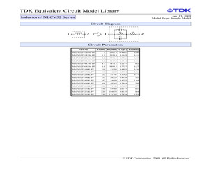
2529 0.035 NLCV32T-R47M-PFR 0.47 1219.4 0.4967 0.038 NLCV32T-R68M-PFR 0.68 1621.0 0.8619 0.045 NLCV32T-1R0M-PFR 1 2475.0 1.3221 0.055 NLCV32T-1R5M-PFR 1.5 2720.7 1.8682 0.095 NLCV32T-2R2M-PFR 2.2 4543.3 1.3766 0.115 NLCV32T-3R3M-PFR 3.3 5761.3 1.7734 0.16 NLCV32T-4R7M-PFR 4.7 7819.7 1.4760 0.2 NLCV32T-6R8M-PFR 6.8 10062 1.7972 0.29 NLCV32T-100K-PFR 10 13347 1.9104 0.42 (c) TDK Corporation, 2009. All Rights Reserved.
 2 Pages, 152 KB, Original
tky Diode and Single-Wire Digital Interface Circuit Description Inductor & Output Capacitor Selection # of LEDs Inductor (L) 10.0H 3, 4, 5 4.7H Part Number Manufacturer LQH43MN100K03 Murata NLCV32T-100K-PFR TDK VLF3010AT-100MR49-1 TDK LQH43MN4R7K03 Murata NLCV32T-4R7M-PFR TDK LPF2010T-4R7M ABCO Min COUT Part Number Manufacturer 1.00F CV105X5R105K25AT AVX/Kyocera 1.00F CV105X5R105K25AT AVX/Kyocera Table 1. Recommended External Components Component Placement and PCB Recomendations Figure 15. Recommended Component Placement PCB Recommendations Input Capacitance In a typical application, the input and output capacitors should be placed as close to the IC as possible; no additional capacitance is needed to ensure proper functionality. However, in a testing environment, where the FAN5341 is typically powered by a power supply with relatively long cables, an additional input capacitor (10F) may be needed to ensure stable functioning. This capacitor should be placed close to where the power supply cables
 12 Pages, 672 KB, Original
cations of the DC-DC converter, although this requirement may be relaxed if a drop in efficiency is acceptable. A list of suggested inductors is in Figure 19. Figure 19: Example 4.7 H inductors Yuden TDK Murata Sumida Wurth Murata Part number CBC2518T4R7M NLCV32T-4R7M-PFR LQM2HPN4R7MGC 0420CDMCBDS-4R7MC 744043004 LQH55DN4R7M03L Current 680 mA 620 mA 800 mA 3400 mA 1550 mA 2700 mA Max DCR 260 m 200 m 225 m 80 m 70 m 57 m Package 2518 (1007) 3225 (1210) 2520 (1008) 4.7 x 4.3 mm 4.8 x 4.8 mm 5750 (2220) The traces from the SW output pins to the inductor and from the output capacitor back to the VDD pins must be routed to minimize the coupling between them. The power supplies must be brought up monotonically and input voltages must not exceed specification at any time. The VDDIO supply to the XS1-U8A-64-FB96 requires a 100nF X5R or X7R ceramic decoupling capacitor placed as close as possible to the supply pins. If the ADC Is used, it requires a 100nF X5R or X7R ceramic decoupling capacitor placed as
 106 Pages, 4768 KB, Original
tky Diode and Single-Wire Digital Interface Circuit Description Inductor & Output Capacitor Selection # of LEDs Inductor (L) 10.0H 3, 4, 5 4.7H Part Number Manufacturer LQH43MN100K03 Murata NLCV32T-100K-PFR TDK VLF3010AT-100MR49-1 TDK LQH43MN4R7K03 Murata NLCV32T-4R7M-PFR TDK LPF2010T-4R7M ABCO Min COUT Part Number Manufacturer 1.00F CV105X5R105K25AT AVX/Kyocera 1.00F CV105X5R105K25AT AVX/Kyocera Table 1. Recommended External Components Component Placement and PCB Recomendations Figure 1. Recommended Component Placement PCB Recommendations Input Capacitance In a typical application, the input and output capacitors should be placed as close to the IC as possible; no additional capacitance is needed to ensure proper functionality. However, in a testing environment, where the FAN5341 is typically powered by a power supply with relatively long cables, an additional input capacitor (10F) may be needed to ensure stable functioning. This capacitor should be placed close to where the power supply cables
 11 Pages, 691 KB, Original
w.onsemi.com 8 Min COUT Part Num ber Manufacturer FAN5341 -- Series Boost LED Driver with Integrated Schottky Diode and Single-Wire Digital Interface Circuit Description 3, 4, 5 4.7H Murata NLCV32T-100K-PFR TDK VLF3010AT-100MR49-1 TDK LQH43MN4R7K03 Murata NLCV32T-4R7M-PFR TDK LPF2010T-4R7M ABCO 1.00F CV105X5R105K25AT AVX/Kyocera 1.00F CV105X5R105K25AT AVX/Kyocera Table 1. Recom m ended External Com ponents Component Placement and PCB Recomendations Figure 15. Recom m ended Com ponent Placem ent PCB Recommendations Input Capacitance In a typical application, the input and output capacitors should be placed as close to the IC as possible; no additional capacitance is needed to ensure proper functionality. How ever, in a testing environment, w here the FAN5341 is typically pow ered by a pow er supply w ith relatively long cables, an additional input capacitor (10F) may be needed to ensure stable functioning. This capacitor should be placed close to w here the pow er supply cables attach to the FAN53
 11 Pages, 470 KB, Original
32T-220K-PF NLCV32T-221K-PF NLCV32T-2R2M-PF NLCV32T-330K-PF NLCV32T-331K-PF NLCV32T-3R3M-PF NLCV32T-470K-PF NLCV32T-4R7M-PF NLCV32T-680K-PF NLCV32T-6R8M-PF NLCV32TR33M-PFR NLCV32T-1R5M-PFR NLCV32T-R47M-PFR NLCV32T-3R3M-PFR NLCV32T-R10M-PFR NLCV32TR15M-PFR NLCV32T-4R7M-PFR NLCV32T-1R0M-PFR NLCV32T-R22M-PFR NLCV32T-R68M-PFR NLCV32T2R2M-PFR NLCV32T-100K-PFR NLCV32T-6R8M-PFR NLCV32T-1R0M-EF NLCV32T-100K-EF NLCV32T-1R5MEF NLCV32T-2R2M-EF NLCV32T-1R0M-EFR NLCV32T-330K-EF NLCV32T-150K-EF NLCV32T-2R2M-EFR NLCV32T-R33M-EFR NLCV32T-151K-EF NLCV32T-R22M-EFR NLCV32T-3R3M-EF NLCV32T-331K-EF NLCV32T100K-EFR NLCV32T-R15M-EFR NLCV32T-470K-EF NLCV32T-R47M-EFR NLCV32T-6R8M-EFR NLCV32T-680KEF NLCV32T-4R7M-EF NLCV32T-6R8M-EF NLCV32T-4R7M-EFR NLCV32T-3R3M-EFR NLCV32T-R68M-EFR NLCV32T-R10M-EFR NLCV32T-1R5M-EFR NLCV32T-221K-EF NLCV32T-220K-EF NLCV32T-470K-PFD NLCV32T-151K-EFD NLCV32T-220K-PFD NLCV32T-101K-EF
 11 Pages, 233 KB, Original
.115 0.16 0.2 0.29 0.42 2850 2600 2400 2100 2000 1900 1700 1400 1200 1000 900 700 600 NLCV32T-R10M-PFR NLCV32T-R15M-PFR NLCV32T-R22M-PFR NLCV32T-R33M-PFR NLCV32T-R47M-PFR NLCV32T-R68M-PFR NLCV32T-1R0M-PFR NLCV32T-1R5M-PFR NLCV32T-2R2M-PFR NLCV32T-3R3M-PFR NLCV32T-4R7M-PFR NLCV32T-6R8M-PFR NLCV32T-100K-PFR 100 10 10 10H Inductance(H) Inductance(H) DC resistance ()20% INDUCTANCE vs. DC SUPERPOSITION CHARACTERISTICS 100 4.7H 2.2H 1 1H 0.47H 4.7H 2.2H 1 1H 0.47H 0.1 0.1H 0.01 1 10H 0.22H 0.22H 0.1 0.01 Self-resonant frequency (MHz)min. 800 500 400 300 250 180 100 80 68 54 46 38 30 10 Frequency (MHz) 100 0.1H 1 10 100 DC current(mA) 1000 10000 IMPEDANCE vs. FREQUENCY CHARACTERISTICS 100000 Impedance() 10000 10H 4.7H 2.2H 1H 1000 100 10 1 0.47H 0.22H 0.1H 1 10 Frequency (MHz) 100 * All specifications are subject to change without notice. 001-03 / 20060921 / e531_nlcv32t_pfr.fm
 2 Pages, 36 KB, Original
cations of the DC-DC converter, although this requirement may be relaxed if a drop in efficiency is acceptable. A list of suggested inductors is in Figure 16. Figure 16: Example 4.7 H inductors Yuden TDK Murata Sumida Wurth Murata Part number CBC2518T4R7M NLCV32T-4R7M-PFR LQM2HPN4R7MGC 0420CDMCBDS-4R7MC 744043004 LQH55DN4R7M03L Current 680 mA 620 mA 800 mA 3400 mA 1550 mA 2700 mA Max DCR 260 m 200 m 225 m 80 m 70 m 57 m Package 2518 (1007) 3225 (1210) 2520 (1008) 4.7 x 4.3 mm 4.8 x 4.8 mm 5750 (2220) The traces from the SW output pins to the inductor and from the output capacitor back to the VDD pins must be routed to minimize the coupling between them. The power supplies must be brought up monotonically and input voltages must not exceed specification at any time. The VDDIO supply to the XS1-U6A-64-FB96 requires a 100nF X5R or X7R ceramic decoupling capacitor placed as close as possible to the supply pins. If the ADC Is used, it requires a 100nF X5R or X7R ceramic decoupling capacitor placed as
 102 Pages, 3794 KB, Original


