describe warranted performance. Typical values, indicated by "typ.," provide expected levels of performance, but are not guaranteed. Table 1. Optical Characteristics1 Package Type Device Code Module Flange-mount Transmitter Plug-in Transmitter 1540A 3540A 10340A 1541A 3541A 10341A 1541B 3541B 10341B Parameter 1541C 3541C 10341C 1541C-E05 3541C-E05 10341C-E18 1740A 3740A 10370A 1741A 3741A 10371A Specifications Wavelength 1310 nm 30 nm 1310 nm 30 nm 1310 nm 30 nm 1310 nm 30 nm 1310 nm 30 nm 1550 nm 30 nm 1550 nm 30 nm Spectral Width, FWHM2, Typ., Max. 10 MHz 10 MHz 10 MHz 10 MHz 10 MHz 10 MHz 10 MHz 4 mW 7 mW 2.4 mW 5 mW 3 mW 6 mW 3 mW 6 mW 3 mW 6 mW 3 mW -- 3 mW -- 15% 15% 15% 15% 15% 15% 15% 0.10 0.16 0.06 0.12 0.06 0.1 0.06 0.1 0.06 0.1 0.05 -- 0.05 -- Optical Power: Min. Typ. Optical Power Stability vs. Temperature dc Modulation Gain: Min. (mW/mA) Typ. (mW/mA) 1. Specifications guaranteed when unit is connected to an optical path with return loss > 35 dB. 2. No RF input. Table 2. dc Power Requ
 8 Pages, 102 KB, Original
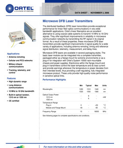
tage ESD TEC Current - - - 100 mA VRPD - - 10 V - - - 1 V - HBM: R = 1500 Ohm, C = 100 pF -500 500 V ITEC continuous -1.9 1.9 A Electrical/Optical Characteristics Optical1 Parameter Specifications Model Number Module Flange-mount Tx Plug-in Tx 1540A 3540A 10340A 1541A 3541A 10341A 1541B 3541B 10341B 1541C 3541C 10341C 1541C-E05 3541C-E05 10341C-E18 1740A 3740A 10370A 1741A 3741A 10371A 1310 nm 30 nm 1310 nm 30 nm 1310 nm 30 nm 1310 nm 30 nm 1310 nm 30 nm 1550 nm 30 nm 1550 nm 30 nm 10 MHz 10 MHz 10 MHz 10 MHz 10 MHz 10 MHz 10 MHz Optical Power, Typical @ ITH + 55 mA 8 mW 8 mW 8 mW 8 mW 8 mW 6 mW 6 mW Optical Power Stability vs. Temperature 15 % 15 % 15 % 15 % 15 % 15 % 15 % 0.14 0.14 0.14 0.14 0.14 0.1 0.1 Wavelength 2 Spectral Width, FWHM , Typ., Max dc Modulation Gain, Typical 1: Specifications guaranteed when unit is connected to an optical path with return loss > 35 dB. 2: No RF input ORTEL, A division of EMCORE Microwave DFB Laser Transmitters DATA SHEET| NOVEMBER 3, 2006 RF Characteristics
 9 Pages, 835 KB, Original
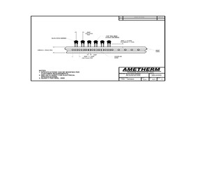
AN BE MODIFIED PER CUSTOMER REQUIREMENTS. 2. SEE DATA SHEET FOR ELECTRICAL SPECIFICATIONS. 3. QUANTY PER REEL 2000 LS100-40 LEAD AMETHERM Reliability Delivered On Time DRWG NAME: DRAWN BY & DATE: TFM DRWG NO.: SL03/NT03 SERIES ON LS100-40 LEAD 02FEB05 AME-10340A SCALE: N/A REV: SHEET: N/C 1
 1 Pages, 71 KB, Original
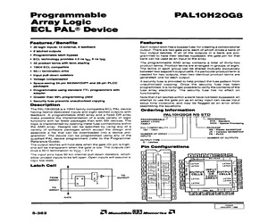
 A 22} 5 a t 25) N LATCH LATCH ig 24] 6 LATCH LATCH 24 [5] R eo) Fy INPUT lea [e] L 9] 7 puTeuT AND puTPuT 6 eit | CELLS | OF | CELLS | M22 a G Tr LoGic t 9 catch =JARRA LatcH 4124 [2] 7 LaTcH a 40 LATCH o 20 [P| a 16 a 14 19) fro] . VEE KC fal 2] = w VEE 10340A JANUARY 1988 ol Monolithic RR Memories olPAL10H20G8 eee ee eee ee errr eee eee eee ees Absolute Maximum Ratings These ratings specify the conditions above which the device may be permanently damaged. AC and DC specifications are not necessarily guaranteed over this range. Supply voltage VEE (VCC1 = VCC2 = VOC9 =O Volts) 0... e ete eb eetennessatteneeeneras -8VtoOV Input voltage Vj (VOC1 = VCC2 = VCC3 =O Volts)... ccc e eee e cet r ence tenets teenttsnsbenenes OV to VEE Output current, QUT CONTINUOUS 0. en een E nde ee dn ee been ebb eee serene bavi ebb eeetattbtneeers 35 mA SUIQE 1.0. cn ce een ne EEE ER EEE EERE ESE A EE e ened HEHE SES ete beep tenesbetteanents 100 mA Storage temperature range, Tytg .-. 6.66. cece cee eee eee een ee Eee
 4 Pages, 172 KB, Scan


