D11 MBR1060 2 C3 220 nF 630 V C13 C11, C12 1500 F R10 10 nF 10 k 50 V 25 V D10 MBR1060 10 9 C6 2.2 nF 1 kV D1-D4 RL207 C19 1 nF 100 V R22 27 R9 150 Q2 2N3904 R12 1.8 R11 0.2 1W R21 200 1/8 W R16 200 R15 1 k 1/8 W R13 1 k 1/8 W R17 1.6 k Q3 2N3904 RTN U2A LTV817A R23 1.8 1W U2B LTV817A C9 470 pF 250 VAC PI-4882-102809 TOPSwitch-GX - Power Factor Corrected Constant Current LED Driver (DER-136) 75 W, 24 V, 3.1 A OUTPUT, 208 - 277 VAC INPUT, SINGLE STAGE PFC, FLYBACK POWER SUPPLY R1 5.1 k L4 330 H R3 R5 VR1 150 k D5 P6KE 100 k 0.5 W 1N4007 200A 2W 1 C6 2.2 nF 1 kV D1-D4 RL207 C2 100 nF 305 VAC R2 5.1 k L2 19 mH NC R4 22 1W C4 15 F 450 V 2 D7 FR305 5 C1 100 nF 305 VAC D6 BYV29-400 RV1 320 VAC F1 5A 10 X 4 F Q5 2N3906 C7 330 F 25 V C C14 100 nF 50 V R23 10.2 k 1% Q1 2N3904 R8 22 R6 1/8 W 300 k 1/8 W C5 22 F 16 V R7 24 C10 33 F 16 V U2B LTV817A C9 2.2 nF 250 VAC R9 150 PI-4979-040208 Q2 2N3904 R20 200 1/8 W R11 0.13 3W R19 10 1/8 W C16 47 F 35 V D8 1N4148 24 V, 3.125 A VR2 1N5
 24 Pages, 4720 KB, Original
5 1/2W R14 0.5 1/2W Out1 U2 1 1 C7 220uF 1 R12 2 50V 0.5 1/2W LED + J4 535676-5 Figure 4. 1 1 8 Pin DIP TH Dual OpAmp & Voltage TSM103ID Ref. STMicroelectronics SO8 SMD U4 Optocoupler Fairchild/LiteOn 4 Pin DIP TH W1 22 Ga solid bus wire Axial TH H11A817A/LTV817A 1 1 2 U3 2 1 STMicroelectronics VIPer12ADIP 1 VIPer12A 1 2 3 4 5 6 U2 2 1 1 Mfg P/N 2 Part Description 2 1 Qty Reference 2 Table 10. 1 AN1916 Current selectable reference board Bill of materials Geometry Mounting VIPer22A current selectable LED driver schematic 15/45 Current selectable reference board Table 11. AN1916 Bill of materials Qty Reference Part Description Mfg P/N Mfg Geometry Radial Mounting 2 C1, C2 10uF 400V Electrolytic TKR2GM100D Compostar TH 1 C3 47pF 1kV Ceramic ECC-D3A470JGE Panasonic 1 C4 22uF 50V Electrolytic EEU-FC1H220 Panasonic 1 C5 4.7nF 250V Ceramic ECK-DNA472ME Panasonic TH 1 C6 0.33uF 50V Ceramic ECU-S1H334KBB Panasonic TH 1 C7 220uF 50V Electrolytic EEU-FC1H221 Panasonic 1 C8 1 TH Radial TH Radial TH 0.1uF 50V
 45 Pages, 586 KB, Original
OMP 23 3 6 13 R55 17 8 GNDP U13 10 14 20 GNDL 9 VCC 7 FBL FMAX 21 RSVD1 5 VREF 4 VCCL 16 ISL 22 GATEL HB GATEH C23 1 MF 25 V 12 R38 4.7 7 C32 C29 100 nF 10 MF 50 V 50 V C31 1 MF 25 V R37 4.7 7 C33 1 MF 25 V C34 1 nF 50 V R56 10 7 R54 1.8 k7 D16 LL4148 U7B LTV817A R53 19.1 k7 1% R49 51.1 k7 R51 1% 22.1 k7 1% C27 1 MF R47 1 k7 R58 10 7 C36 1 nF 50 V Q11 IRFIB7N 50LPBF Q10 IRFIB7N 50LPBF L6 Ferrite Bead (3.5 x 4.45 mm) C35 1 nF 50 V L7 Ferrite Bead (3.5 x 4.45 mm) C30 1 nF 50 V R52 19.1 k7 1% GATEL C40 100 nF 630 V C39 22 nF 1250 V R59 0.1 7 2W 6 5 14 9,10 11,12 7,8 T2 13 C55 2.2 uF 50 V C54 2.2 uF 50 V C38 1800 MF 35 V C53 1800 MF 35 V C43 R61 10 MF 10 k7 25 V Q12 S14408DY D11 LL4148 R60 100 7 D9B D10B 16CTT100 D10 A D9A 16CTT100 L8 3.3 uH C37 1800 MF 35 V Q13 MMBT3906 R71 100 7 R57 10 7 Q15 MMBT3904 R73 10 k7 C50 220 nF R90 10 k7 Q14 MMBT3906 R70 C49 10 k7 10 nF C44 10 MF 25 V C52 100 MF 35 V D13 LL4148 VR7 2MM5245B-7 15 V C48 1 MF 50 V R72 1 k7 U7A LTV817A R62 3.9 k7 D12 LL4148 R63 1
 28 Pages, 733 KB, Original
72) 9 W, 70 V, 130 mA OUTPUT, 90 - 132 VAC INPUT BUCK CONVERTER 70 V, 130 mA D1 1N4007 D2 1N4007 L1 5 mH 108 - 132 VAC N C1 100 nF 275 VAC D3 1N4007 R5 1 M R4 7.5 1/2 W RTN LinkSwitch-TN U1 LNK306PN D D4 1N4007 C5 33 nF 100 V R3 100 1/8 W R2 470 1/8 W U2A LTV817A L2 1.1 mH C2 22 F 200 V VR2 1N5258B 36 V C4 47 F 200 V D5 BYV26B F1 1A L VR1 1N5259B 39 V PI-4988-042408 FB BP U2B LTV817A C3 100 nF 50 V S LinkSwitch-TN - Low Cost Dimmable LED Ballast (DI-171) 9 W, 70 V, 130 A OUTPUT, 108 - 132 VAC INPUT BUCK-BOOST 70 V, 130 mA D5 1N4007 D6 1N4007 D10 1N4007 D1 BYV26B C2 22 F 200 V L F1 2A 108 - 132 VAC N L1 1500 H R1 4.7 1/2 W C10 47 nF 275 VAC R16 4.7 k C6 47 nF 275 VAC D4 1N4007 L3 2.2 mH D2 1N4007 D3 1N4007 D7 1N4007 D8 1N4007 C1 22 F 200 V D LinkSwitch-TN U1 LNK306PN R12 33 k 1/8 W U2B LTV817A R7 220 k 1/8 W C7 1 nF 100 V RTN Q1 2N3906 C4 100 nF 50 V R9 1 M R13 1 M R6 33 k 1/8 W FB BP C9 33 nF 100 V R10 R11 220 7.5 1/8 W 1/2 W U2A LTV817A S R4 100 k 1/2 W R8
 6 Pages, 1329 KB, Original
 PLC810PG 10 14 20 GNDL 9 VCC 7 FBL FMAX 21 RSVD1 5 VREF 4 VCCL 16 ISL 22 GATEL HB GATEH C23 1 F 25 V 12 R38 4.7 C32 C29 100 nF 10 F 50 V 50 V C31 1 F 25 V R37 4.7 C33 1 F 25 V L7 Ferrite Bead (3.5 x 4.45 mm) R47 1 k R58 10 R56 10 R54 1.8 k D16 LL4148 U7B LTV817A R53 19.1 k 1% R49 51.1 k R51 1% 22.1 k 1% C27 1 F L6 Ferrite Bead (3.5 x 4.45 mm) C30 C34 C35 1 nF 1 nF 1 nF 200 V 200 V 200 V R52 19.1 k 1% GATEL Bead 3 Ferrite Bead C36 1 nF 200 V D18 LL4148 Q11 IRFIB5N50 LPBF D17 LL4148 Q10 IRFIB5N50 LPBF C40 100 nF 630 V 6 5 R59 0.1 2W C39 TP26 22 nF 1250 V 14 9,10 11,12 7,8 T2 13 C53 1800 F 35 V C38 1800 F 35 V C43 R61 10 F 10 k 25 V Q12 SI4408DY D11 LL4148 R60 100 D9B D10B 16CTT100 D10A D9A 16CTT100 L8 3.3 H C37 1800 F 35 V R71 100 R57 10 R73 10 k C50 220 nF R69 10 k Q13 MMBT3906 Q14 MMBT3906 C49 10 nF 200 V Q15 MMBT3904 C44 10 F 25 V R70 10 k C52 100 F 35 V D13 LL4148 VR7 2MM5245B-7 15 V TP21 TP18 C48 1 F 50 V R72 1 k U7A LTV817A TP24 R62 3.9 k D12 LL4148 1% R68 10 k PI-5275-061109 U8
 26 Pages, 944 KB, Original
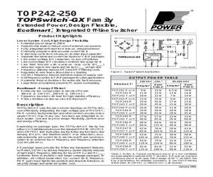
S R6 150 C6 0.1 F T1 D R2 9.09 k N D2 1N4148 R1 4.7 M 1/2 W F1 3.15 A L C12 220 F 35 V C11 560 F 35 V RTN R4 2 M 1/2 W CX1 100 nF 250 VAC C10 560 F 35 V D1 UF4005 L1 20 mH J1 D8 MBR1060 12 V @ 2.5 A TOPSwitch-GX U1 TOP244Y CONTROL C L X R5 6.8 F R8 150 U2 LTV817A VR2 1N5240C 10 V, 2% C5 47 F 10 V PI-2657-081204 Figure 41. 30 W Power Supply using External Current Limit Programming and Line Sensing for UV and OV. 20 N 4/05 TOP242-250 increase efficiency. This design delivers 70 W at 19 V, from an 85 VAC to 265 VAC input, at an ambient of 40 C, in a small sealed adapter case (4" x 2.15" x 1"). Full load efficiency is 85% at 85 VAC rising to 90% at 230 VAC input. reduce Zener clamp dissipation. With a switching frequency of 132 kHz, a PQ26/20 core can be used to provide 70 W. To maximize efficiency, by reducing winding losses, two output windings are used each with their own dual 100 V Schottky rectifier (D2 and D3). The frequency reduction feature of the TOPSwitch-GX eliminates any dummy loading to
 52 Pages, 2184 KB, Original
D2 1N4148 D S R2 9.09 k N R6 150 C6 0.1 F T1 R1 4.7 M 1/2 W F1 3.15 A L C12 220 F 35 V C11 560 F 35 V RTN R4 2 M 1/2 W CX1 100 nF 250 VAC C10 560 F 35 V D1 UF4005 L1 20 mH J1 D8 MBR1060 12 V @ 2.5 A TOPSwitch-GX U1 TOP244Y CONTROL C L X R5 6.8 F R8 150 U2 LTV817A VR2 1N5240C 10 V, 2% C5 47 F 10 V PI-2657-081204 Figure 41. 30 W Power Supply using External Current Limit Programming and Line Sensing for UV and OV. 20 O 11/05 TOP242-250 increase efficiency. This design delivers 70 W at 19 V, from an 85 VAC to 265 VAC input, at an ambient of 40 C, in a small sealed adapter case (4" x 2.15" x 1"). Full load efficiency is 85% at 85 VAC rising to 90% at 230 VAC input. reduce Zener clamp dissipation. With a switching frequency of 132 kHz, a PQ26/20 core can be used to provide 70 W. To maximize efficiency, by reducing winding losses, two output windings are used each with their own dual 100 V Schottky rectifier (D2 and D3). The frequency reduction feature of the TOPSwitch-GX eliminates any dummy loading to
 52 Pages, 1205 KB, Original
9 R5 TOPSwitch-GX AC-DC Seminar 10 6.8 VR2 1N5240C 10 V, 2% C5 Sales Representatives and Distributors 11 47 F 10 V N PI-2657-040501 Figure 41. 30 W Power Supply using External Current Limit Programming and Line Sensing for UV and OV. 20 8 C R2 9.09 k L U2 LTV817A LinkSwitch & TinySwitch-II AC-DC Seminar U1 D 7 K 9/03 TOP242-250 A High Efficiency, Enclosed, 70 W, Universal Adapter Supply The circuit shown in figure 42 takes advantage of several of the TOPSwitch-GX features to reduce cost, power supply size and increase efficiency. This design delivers 70 W at 19 V, from an 85 to 265 VAC input, at an ambient of 40 C, in a small sealed adapter case (4" x 2.15" x 1"). Full load efficiency is 85% at 85 VAC rising to 90% at 230 VAC input. damage. Capacitor C11 has been added in parallel with VR1 to reduce Zener clamp dissipation. With a switching frequency of 132 kHz a PQ26/20 core can be used to provide 70 W. To maximize efficiency, by reducing winding losses, two output windings are used each with th
 52 Pages, 466 KB, Original
 1 nF 150 L3 3.3 H R3 68 k 2W C3 4.7 nF 1 kV BR1 600 V 2A J1 L N C10 560 F 35 V C12 220 F 35 V C11 560 F 35 V D1 UF4005 RTN D2 1N4148 R4 2 M 1/2 W L1 20 mH C1 68 F 400 V CX1 100 nF 250 VAC D8 MBR1060 12 V @ 2.5 A R1 4.7 M 1/2 W D R2 9.09 k L X F R8 150 U2 LTV817A TOPSwitch-GX CONTROL S F1 3.15 A C6 0.1 F T1 U1 TOP244Y R6 150 C R5 6.8 VR2 1N5240C 10 V, 2% C5 47 F 10 V PI-2657-040501 Figure 41. 30 W Power Supply using External Current Limit Programming and Line Sensing for UV and OV. August 8, 2000 E 7/01 21 TOP242-249 Capacitor C11 has been added in parallel with VR1 to reduce Zener clamp dissipation. With a switching frequency of 132 kHz a PQ26/20 core can be used to provide 70 W. To maximize efficiency, by reducing winding losses, two output windings are used each with their own dual 100 V Schottky rectifier (D2 and D3). The frequency reduction feature of the TOPSwitch-GX eliminates any dummy loading to maintain regulation at no-load and reduces the no-load consumption of the power supply to onl
 48 Pages, 767 KB, Original
ss to the fuse and replace the existing fuse with the new fuse. SIDE VIEW GLASS FRONT W415-1527 / 07.16.15 FUSE COVER N 4 3 S1 V+ AC 1M R17 6mH 400V 22U C14 L2 400V 22U 2KBP06M C13 V- AC P-NI F1 TNY1 TNY278PN 4 GND 6.3*0.58 PH-6 2 7 1 GND 6 GND GND C4 U1A LTV817A EF1 C11 C10 2.2nF/250VAC C12 16V 10U R3 10K t +5V 2 1 D7 FR106 D8 P6KE200 2.2nF/250VAC HS0038 5-8 R16 2M R15 2M FUSE2 TEMP_BRK PTC C6 104 5v 2.4*2 1 2 TEMP GND BUZ1 +5V D4 27 R13 6.3*0.8 P-L C7 10K R8 SS8050 T3 1K R2 2.4*7 C2 104 R14 1K 10K R5 GND D6 12V C8 +12V R1 GND P5.3 P5.2 12 11 P0.4 P4.1/AIN1 P4.2/AIN2 VSS 10 IC1 Vin 16 1 15 2 P0.1 100/0.5W C5 104 5 GND 100U 16V 3.3uH L1 GND GND GND 1 2 3 4 5 6 SIP2 510 R4 D1 4007 LTV817A U1B GND 35V 680uF SB3100 390PF C9 3 C1 VDD SN8P2722 20 1KU/16V Vout 7805 104 C3 +5V P0.2 P5.1 P5.0 P0.7 P0.5 P0.6 3 510 10R12 510 9 R11 510 8 R10 6 7 GND 8050 T6 T7 8050 GND GND T5 8050 1N4007 +12V 1N4007 +12V 1N4007 +12V 100 R? 180 100 R? 100 180 R? 180 R? D5 D3 D2 LED7 LED5 LED7 LED5 MOTOR 6.3*0.8
 40 Pages, 1823 KB, Original
D2 1N4148 D S R2 9.09 k N R6 150 C6 0.1 F T1 R1 4.7 M 1/2 W F1 3.15 A L C12 220 F 35 V C11 560 F 35 V RTN R4 2 M 1/2 W CX1 100 nF 250 VAC C10 560 F 35 V D1 UF4005 L1 20 mH J1 D8 MBR1060 12 V @ 2.5 A TOPSwitch-GX U1 TOP244Y CONTROL C L X R5 6.8 F R8 150 U2 LTV817A VR2 1N5240C 10 V, 2% C5 47 F 10 V PI-2657-081204 Figure 41. 30 W Power Supply using External Current Limit Programming and Line Sensing for UV and OV. 20 M 12/04 TOP242-250 increase efficiency. This design delivers 70 W at 19 V, from an 85 VAC to 265 VAC input, at an ambient of 40 C, in a small sealed adapter case (4" x 2.15" x 1"). Full load efficiency is 85% at 85 VAC rising to 90% at 230 VAC input. reduce Zener clamp dissipation. With a switching frequency of 132 kHz, a PQ26/20 core can be used to provide 70 W. To maximize efficiency, by reducing winding losses, two output windings are used each with their own dual 100 V Schottky rectifier (D2 and D3). The frequency reduction feature of the TOPSwitch-GX eliminates any dummy loading to
 52 Pages, 2180 KB, Original
D2 1N4148 D S R2 9.09 k N R6 150 C6 0.1 F T1 R1 4.7 M 1/2 W F1 3.15 A L C12 220 F 35 V C11 560 F 35 V RTN R4 2 M 1/2 W CX1 100 nF 250 VAC C10 560 F 35 V D1 UF4005 L1 20 mH J1 D8 MBR1060 12 V @ 2.5 A TOPSwitch-GX U1 TOP244Y CONTROL C L X R5 6.8 F R8 150 U2 LTV817A VR2 1N5240C 10 V, 2% C5 47 F 10 V PI-2657-081204 Figure 41. 30 W Power Supply using External Current Limit Programming and Line Sensing for UV and OV. 20 O 11/05 TOP242-250 increase efficiency. This design delivers 70 W at 19 V, from an 85 VAC to 265 VAC input, at an ambient of 40 C, in a small sealed adapter case (4" x 2.15" x 1"). Full load efficiency is 85% at 85 VAC rising to 90% at 230 VAC input. reduce Zener clamp dissipation. With a switching frequency of 132 kHz, a PQ26/20 core can be used to provide 70 W. To maximize efficiency, by reducing winding losses, two output windings are used each with their own dual 100 V Schottky rectifier (D2 and D3). The frequency reduction feature of the TOPSwitch-GX eliminates any dummy loading to
 53 Pages, 2225 KB, Original
S R6 150 C6 0.1 F T1 D R2 9.09 k N D2 1N4148 R1 4.7 M 1/2 W F1 3.15 A L C12 220 F 35 V C11 560 F 35 V RTN R4 2 M 1/2 W CX1 100 nF 250 VAC C10 560 F 35 V D1 UF4005 L1 20 mH J1 D8 MBR1060 12 V @ 2.5 A TOPSwitch-GX U1 TOP244Y CONTROL C L X R5 6.8 F R8 150 U2 LTV817A VR2 1N5240C 10 V, 2% C5 47 F 10 V PI-2657-081204 Figure 41. 30 W Power Supply using External Current Limit Programming and Line Sensing for UV and OV. 20 N 4/05 TOP242-250 increase efficiency. This design delivers 70 W at 19 V, from an 85 VAC to 265 VAC input, at an ambient of 40 C, in a small sealed adapter case (4" x 2.15" x 1"). Full load efficiency is 85% at 85 VAC rising to 90% at 230 VAC input. reduce Zener clamp dissipation. With a switching frequency of 132 kHz, a PQ26/20 core can be used to provide 70 W. To maximize efficiency, by reducing winding losses, two output windings are used each with their own dual 100 V Schottky rectifier (D2 and D3). The frequency reduction feature of the TOPSwitch-GX eliminates any dummy loading to
 52 Pages, 2179 KB, Original
N C10 560 F 35 V C11 560 F 35 V C12 220 F 35 V D1 UF4005 RTN D2 1N4148 R4 2 M 1/2 W L1 20 mH C1 68 F 400 V CX1 100 nF 250 VAC D8 MBR1060 12 V @ 2.5 A R1 4.7 M 1/2 W D R2 9.09 k L TOPSwitch-GX CONTROL S F1 3.15 A C6 0.1 F T1 U1 TOP244Y X R6 150 F R8 150 U2 LTV817A C R5 6.8 VR2 1N5240C 10 V, 2% C5 47 F 10 V PI-2657-040501 Figure 41. 30 W Power Supply using External Current Limit Programming and Line Sensing for UV and OV. G 1/02 21 TOP242-250 A High Efficiency, Enclosed, 70 W, Universal Adapter Supply The circuit shown in figure 42 takes advantage of several of the TOPSwitch-GX features to reduce cost, power supply size and increase efficiency. This design delivers 70 W at 19 V, from an 85 to 265 VAC input, at an ambient of 40 C, in a small sealed adapter case (4" x 2.15" x 1"). Full load efficiency is 85% at 85 VAC rising to 90% at 230 VAC input. damage. Capacitor C11 has been added in parallel with VR1 to reduce Zener clamp dissipation. With a switching frequency of 132 kHz a PQ26/20 core can be
 52 Pages, 449 KB, Original
150 L3 3.3 H R3 68 K 2W C3 4.7 nF 1KV BR1 600 V 2A J1 L N C10 560 F 35 V C12 220 F 35 V C11 560 F 35 V D1 UF4005 RTN D2 1N4148 R4 2 M 1/2 W L1 20 mH C1 68 F 400V CX1 100 nF 250 VAC D8 MBR1060 12 V @ 2.5A R1 4.7 M 1/2 W U1 TOP244Y R2 9.09 K L X F R8 150 U2 LTV817A TOPSwitch-GX CONTROL S F1 3.15 A C6 0.1 F T1 D R6 150 C R5 6.8 VR2 1N5240C 10 V, 2% C5 47 F 10 V PI-2657-071900 Figure 41. 30 W Power Supply using External Current Limit Programming and Line Sensing for UV and OV. August 8, 2000 D 11/00 21 TOP242-249 Capacitor C11 has been added in parallel with VR1 to reduce zener clamp dissipation. With a switching frequency of 132 kHz a PQ26/20 core can be used to provide 70 W. To maximize efficiency, by reducing winding losses, two output windings are used each with there own dual 100 V Schottky rectifier (D2 and D3). The frequency reduction feature of the TOPSwitch-GX eliminates any dummy loading to maintain regulation at no-load and reduces the no-load consumption of the power supply to only 520 mW
 48 Pages, 433 KB, Original


