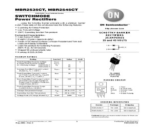
ckage Shipping MBR2535CT TO-220 50 Units/Rail MBR2545CT TO-220 50 Units/Rail Preferred devices are recommended choices for future use and best overall value. Semiconductor Components Industries, LLC, 2000 October, 2000 - Rev. 2 1 Publication Order Number: MBR2535CT/D MBR2535CT, MBR2545CT THERMAL CHARACTERISTICS (Per Diode Leg) Characteristic Maximum Thermal Resistance, Junction to Case Symbol MBR2535CT MBR2545CT Unit RJC 1.5 1.5 C/W 0.73 0.82 0.73 0.82 40 0.2 40 0.2 ELECTRICAL CHARACTERISTICS (Per Diode Leg) Maximum Instantaneous Forward Voltage (Note 1.) (iF = 30 Amps, TC = 125C) (iF = 30 Amps, TC = 25C) vF Maximum Instantaneous Reverse Current (Note 1.) (Rated dc Voltage, TC = 125C) (Rated dc Voltage, TC = 25C) iR Volts mA 100 70 200 100 50 TJ = 125C 30 20 100C 25C 10 7.0 5.0 3.0 2.0 1.0 0 0.2 0.4 0.6 40 20 10 4.0 2.0 1.0 0.4 0.2 0.1 0.04 0.02 0.01 0.004 0.002 TJ = 150C IR , REVERSE CURRENT (mA) i F, INSTANTANEOUS FORWARD CURRENT (AMPS) 1. Pulse Test: Pulse Width = 300 s, Duty Cycle 2.0%. 0.8 1
 4 Pages, 57 KB, Original
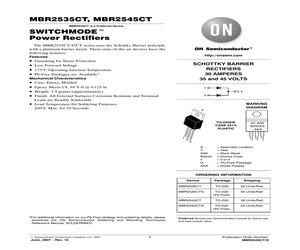
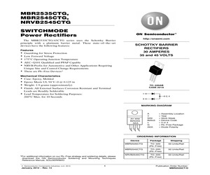
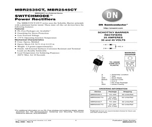
on on our Pb-Free strategy and soldering details, please download the ON Semiconductor Soldering and Mounting Techniques Reference Manual, SOLDERRM/D. (c) Semiconductor Components Industries, LLC, 2014 September, 2014 - Rev. 15 1 Publication Order Number: MBR2535CT/D MBR2535CTG, MBR2545CTG MAXIMUM RATINGS Rating Symbol Value Unit Peak Repetitive Reverse Voltage Working Peak Reverse Voltage DC Blocking Voltage MBR2535CTG MBR2545CTG VRRM VRWM VR V Average Rectified Forward Current (Rated VR, TC = 160C) Per Device Per Diode IF(AV) Peak Repetitive Forward Current per Diode Leg (Rated VR, Square Wave, 20 kHz, TC = 150C) IFRM Non-Repetitive Peak Surge Current per Diode Leg (Surge Applied at Rated Load Conditions, Halfwave, Single Phase, 60 Hz) IFSM Peak Repetitive Reverse Surge Current (2.0 s, 1.0 kHz) IRRM 1.0 A Storage Temperature Range Tstg -65 to +175 C Operating Junction Temperature (Note 1) TJ -65 to +175 C Voltage Rate of Change (Rated VR) dv/dt 10,000 V/s ESD Ratings: Machine Model = C Human Bo
 4 Pages, 85 KB, Original
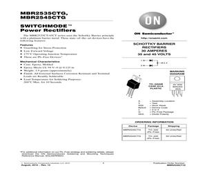
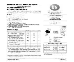
2007 June, 2007 - Rev. 10 1 Package Shipping TO-220 50 Units/Rail TO-220 (Pb-Free) 50 Units/Rail TO-220 50 Units/Rail TO-220 (Pb-Free) 50 Units/Rail Preferred devices are recommended choices for future use and best overall value. Publication Order Number: MBR2535CT/D MBR2535CT, MBR2545CT MAXIMUM RATINGS Rating Symbol Peak Repetitive Reverse Voltage Working Peak Reverse Voltage DC Blocking Voltage MBR2535CT MBR2545CT Value VRRM VRWM VR Average Rectified Forward Current (Rated VR, TC = 160C) Unit V 35 45 IF(AV) 30 A Peak Repetitive Forward Current, per Diode Leg (Rated VR, Square Wave, 20 kHz, TC = 150C) IFRM 30 A Non-Repetitive Peak Surge Current per Diode Leg (Surge Applied at Rated Load Conditions, Halfwave, Single Phase, 60 Hz) IFSM 150 A Peak Repetitive Reverse Surge Current (2.0 s, 1.0 kHz) IRRM 1.0 A Storage Temperature Range Tstg -65 to +175 C Operating Junction Temperature (Note 1) TJ -65 to +175 C Voltage Rate of Change (Rated VR) dv/dt 10,000 V/s ESD Ratings: Machine Model = C ESD Rating
 4 Pages, 74 KB, Original
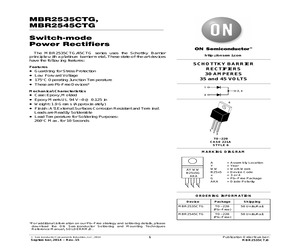
ation on our Pb-Free strategy and soldering details, please download the ON Semiconductor Soldering and Mounting Techniques Reference Manual, SOLDERRM/D. (c) Semiconductor Components Industries, LLC, 2010 August, 2010 - Rev. 12 1 Publication Order Number: MBR2535CT/D MBR2535CTG, MBR2545CTG MAXIMUM RATINGS Rating Symbol Peak Repetitive Reverse Voltage Working Peak Reverse Voltage DC Blocking Voltage MBR2535CT MBR2545CT Average Rectified Forward Current (Rated VR, TC = 160C) Per Device Per Diode Value VRRM VRWM VR Unit V 35 45 IF(AV) 30 15 A Peak Repetitive Forward Current, per Diode Leg (Rated VR, Square Wave, 20 kHz, TC = 150C) IFRM 30 A Non-Repetitive Peak Surge Current per Diode Leg (Surge Applied at Rated Load Conditions, Halfwave, Single Phase, 60 Hz) IFSM 150 A Peak Repetitive Reverse Surge Current (2.0 s, 1.0 kHz) IRRM 1.0 A Storage Temperature Range Tstg -65 to +175 C Operating Junction Temperature (Note 1) TJ -65 to +175 C Voltage Rate of Change (Rated VR) dv/dt 10,000 V/s ESD Ratings: Ma
 4 Pages, 93 KB, Original
e Package Shipping MBR2535CT TO-220 50 Units/Rail MBR2545CT TO-220 50 Units/Rail Preferred devices are recommended choices for future use and best overall value. Semiconductor Components Industries, LLC, 2001 May, 2001 - Rev. 3 1 Publication Order Number: MBR2535CT/D MBR2535CT, MBR2545CT THERMAL CHARACTERISTICS (Per Diode Leg) Characteristic Maximum Thermal Resistance, Junction to Case Symbol MBR2535CT MBR2545CT Unit RJC 1.5 1.5 C/W 0.73 0.82 0.73 0.82 40 0.2 40 0.2 ELECTRICAL CHARACTERISTICS (Per Diode Leg) Maximum Instantaneous Forward Voltage (Note 1.) (iF = 30 Amps, TC = 125C) (iF = 30 Amps, TC = 25C) vF Maximum Instantaneous Reverse Current (Note 1.) (Rated dc Voltage, TC = 125C) (Rated dc Voltage, TC = 25C) iR Volts mA 100 70 200 100 50 TJ = 125C 30 20 100C 25C 10 7.0 5.0 3.0 2.0 1.0 0 0.2 0.4 0.6 40 20 10 4.0 2.0 1.0 0.4 0.2 0.1 0.04 0.02 0.01 0.004 0.002 TJ = 150C IR , REVERSE CURRENT (mA) i F, INSTANTANEOUS FORWARD CURRENT (AMPS) 1. Pulse Test: Pulse Width = 300 s, Duty Cycle 2.0%. 0.8 1
 4 Pages, 57 KB, Original
 2008 May, 2008 - Rev. 11 1 Package Shipping TO-220 50 Units/Rail TO-220 (Pb-Free) 50 Units/Rail TO-220 50 Units/Rail TO-220 (Pb-Free) 50 Units/Rail Preferred devices are recommended choices for future use and best overall value. Publication Order Number: MBR2535CT/D MBR2535CT, MBR2545CT MAXIMUM RATINGS Rating Symbol Peak Repetitive Reverse Voltage Working Peak Reverse Voltage DC Blocking Voltage MBR2535CT MBR2545CT Value VRRM VRWM VR Average Rectified Forward Current (Rated VR, TC = 160C) Unit V 35 45 IF(AV) 30 A Peak Repetitive Forward Current, per Diode Leg (Rated VR, Square Wave, 20 kHz, TC = 150C) IFRM 30 A Non-Repetitive Peak Surge Current per Diode Leg (Surge Applied at Rated Load Conditions, Halfwave, Single Phase, 60 Hz) IFSM 150 A Peak Repetitive Reverse Surge Current (2.0 s, 1.0 kHz) IRRM 1.0 A Storage Temperature Range Tstg -65 to +175 C Operating Junction Temperature (Note 1) TJ -65 to +175 C Voltage Rate of Change (Rated VR) dv/dt 10,000 V/s ESD Ratings: Machine Model = C ESD Rating
 4 Pages, 117 KB, Original
 SOLDERRM/D. Semiconductor Components Industries, LLC, 2012 January, 2012 - Rev. 13 1 Package Shipping MBR2535CTG TO-220 (Pb-Free) 50 Units/Rail MBR2545CTG TO-220 (Pb-Free) 50 Units/Rail NRVB2545CTG TO-220 (Pb-Free) 50 Units/Rail Publication Order Number: MBR2535CT/D MBR2535CTG, MBR2545CTG, NRVB2545CTG MAXIMUM RATINGS Rating Symbol Value Unit Peak Repetitive Reverse Voltage Working Peak Reverse Voltage DC Blocking Voltage MBR2535CTG MBR2545CTG, NRVB2545CTG VRRM VRWM VR V Average Rectified Forward Current (Rated VR, TC = 160C) Per Device Per Diode IF(AV) Peak Repetitive Forward Current per Diode Leg (Rated VR, Square Wave, 20 kHz, TC = 150C) IFRM Non-Repetitive Peak Surge Current per Diode Leg (Surge Applied at Rated Load Conditions, Halfwave, Single Phase, 60 Hz) IFSM Peak Repetitive Reverse Surge Current (2.0 s, 1.0 kHz) IRRM 1.0 A Storage Temperature Range Tstg -65 to +175 C Operating Junction Temperature (Note 1) TJ -65 to +175 C Voltage Rate of Change (Rated VR) dv/dt 10,000 V/s ESD Ratings:
 4 Pages, 123 KB, Original
g and Mounting Techniques Reference Manual, SOLDERRM/D. (c) Semiconductor Components Industries, LLC, 2012 May, 2012 - Rev. 14 1 Package Shipping MBR2535CTG TO-220 (Pb-Free) 50 Units/Rail MBR2545CTG TO-220 (Pb-Free) 50 Units/Rail Publication Order Number: MBR2535CT/D MBR2535CTG, MBR2545CTG MAXIMUM RATINGS Rating Symbol Value Unit Peak Repetitive Reverse Voltage Working Peak Reverse Voltage DC Blocking Voltage MBR2535CTG MBR2545CTG VRRM VRWM VR V Average Rectified Forward Current (Rated VR, TC = 160C) Per Device Per Diode IF(AV) Peak Repetitive Forward Current per Diode Leg (Rated VR, Square Wave, 20 kHz, TC = 150C) IFRM Non-Repetitive Peak Surge Current per Diode Leg (Surge Applied at Rated Load Conditions, Halfwave, Single Phase, 60 Hz) IFSM Peak Repetitive Reverse Surge Current (2.0 s, 1.0 kHz) IRRM 1.0 A Storage Temperature Range Tstg -65 to +175 C Operating Junction Temperature (Note 1) TJ -65 to +175 C Voltage Rate of Change (Rated VR) dv/dt 10,000 V/s ESD Ratings: Machine Model = C Human Bo
 4 Pages, 90 KB, Original
ormation on our Pb-Free strategy and soldering details, please download the ON Semiconductor Soldering and Mounting Techniques Reference Manual, SOLDERRM/D. Semiconductor Components Industries, LLC, 2005 February, 2005 - Rev. 5 1 Publication Order Number: MBR2535CT/D MBR2535CT, MBR2545CT THERMAL CHARACTERISTICS (Per Diode Leg) Characteristic Maximum Thermal Resistance, Junction-to-Case Symbol MBR2535CT MBR2545CT Unit RJC 1.5 1.5 C/W 0.73 0.82 0.73 0.82 40 0.2 40 0.2 ELECTRICAL CHARACTERISTICS (Per Diode Leg) Maximum Instantaneous Forward Voltage (Note 1) (iF = 30 Amps, TC = 125C) (iF = 30 Amps, TC = 25C) vF Maximum Instantaneous Reverse Current (Note 1) (Rated dc Voltage, TC = 125C) (Rated dc Voltage, TC = 25C) iR V mA 100 70 200 100 50 40 20 10 4.0 2.0 1.0 0.4 0.2 0.1 0.04 0.02 0.01 0.004 0.002 TJ = 125C 30 20 100C 25C 10 7.0 5.0 3.0 2.0 1.0 0 0.2 0.4 0.6 TJ = 150C IR , REVERSE CURRENT (mA) i F, INSTANTANEOUS FORWARD CURRENT (AMPS) 1. Pulse Test: Pulse Width = 300 s, Duty Cycle 2.0%. 0.8 1.0 125
 4 Pages, 57 KB, Original
2006 April, 2006 - Rev. 7 1 Package Shipping TO-220 50 Units/Rail TO-220 (Pb-Free) 50 Units/Rail TO-220 50 Units/Rail TO-220 (Pb-Free) 50 Units/Rail Preferred devices are recommended choices for future use and best overall value. Publication Order Number: MBR2535CT/D MBR2535CT, MBR2545CT MAXIMUM RATINGS Rating Symbol Peak Repetitive Reverse Voltage Working Peak Reverse Voltage DC Blocking Voltage MBR2535CT MBR2545CT Value VRRM VRWM VR Average Rectified Forward Current (Rated VR, TC = 130C) Unit V 35 45 IF(AV) 30 A Peak Repetitive Forward Current, per Diode Leg (Rated VR, Square Wave, 20 kHz, TC = 130C) IFRM 30 A Non-Repetitive Peak Surge Current per Diode Leg (Surge Applied at Rated Load Conditions, Halfwave, Single Phase, 60 Hz) IFSM 150 A Peak Repetitive Reverse Surge Current (2.0 s, 1.0 kHz) IRRM 1.0 A Storage Temperature Range Tstg -65 to +175 C Operating Junction Temperature (Note 1) TJ -65 to +175 C Voltage Rate of Change (Rated VR) dv/dt 10,000 V/s ESD Ratings: Machine Model = C ESD Rating
 4 Pages, 53 KB, Original
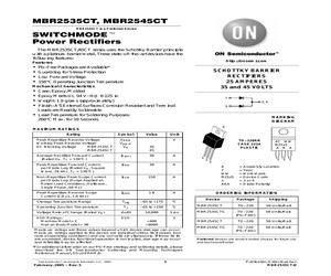
MBR2535CT/D SEMICONDUCTOR TECHNICAL DATA . . . using the Schottky Barrier principle with a platinum barrier metal. These state-of-the-art devices have the following features: * * * * Guardring for Stress Protection Low Forward Voltage 150C Operating Junction Temperature Guaranteed Reverse Avalanche MBR2545CT is a Motorola Preferred Device SCHOTTKY BARRIER RECTIFIERS 30 AMPERES 35 and 45 VOLTS Mechanical Characteristics: * Case: Epoxy, Molded * Weight: 1.9 grams (approximately) * Finish: All External Surfaces Corrosion Resistant and Terminal Leads are Readily Solderable * Lead Temperature for Soldering Purposes: 260C Max. for 10 Seconds * Shipped 50 units per plastic tube * Marking: B2535, B2545 4 1 2, 4 1 2 3 3 CASE 221A-06 TO-220AB PLASTIC MAXIMUM RATINGS Symbol MBR2535CT MBR2545CT Unit Peak Repetitive Reverse Voltage Working Peak Reverse Voltage DC Blocking Voltage Rating VRRM VRWM VR 35 45 Volts Average Rectified Forward Current (Rated VR) TC = 130C IF(AV) 30 30 Amps Peak Repetitive Forward Cu
 4 Pages, 65 KB, Original
, 2006 May, 2006 - Rev. 8 1 Package Shipping TO-220 50 Units/Rail TO-220 (Pb-Free) 50 Units/Rail TO-220 50 Units/Rail TO-220 (Pb-Free) 50 Units/Rail Preferred devices are recommended choices for future use and best overall value. Publication Order Number: MBR2535CT/D MBR2535CT, MBR2545CT MAXIMUM RATINGS Rating Symbol Peak Repetitive Reverse Voltage Working Peak Reverse Voltage DC Blocking Voltage MBR2535CT MBR2545CT Value VRRM VRWM VR Average Rectified Forward Current (Rated VR, TC = 160C) Unit V 35 45 IF(AV) 30 A Peak Repetitive Forward Current, per Diode Leg (Rated VR, Square Wave, 20 kHz, TC = 150C) IFRM 30 A Non-Repetitive Peak Surge Current per Diode Leg (Surge Applied at Rated Load Conditions, Halfwave, Single Phase, 60 Hz) IFSM 150 A Peak Repetitive Reverse Surge Current (2.0 s, 1.0 kHz) IRRM 1.0 A Storage Temperature Range Tstg -65 to +175 C Operating Junction Temperature (Note 1) TJ -65 to +175 C Voltage Rate of Change (Rated VR) dv/dt 10,000 V/s ESD Ratings: Machine Model = C ESD Rating
 4 Pages, 95 KB, Original
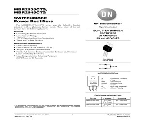
on on our Pb-Free strategy and soldering details, please download the ON Semiconductor Soldering and Mounting Techniques Reference Manual, SOLDERRM/D. (c) Semiconductor Components Industries, LLC, 2014 September, 2014 - Rev. 15 1 Publication Order Number: MBR2535CT/D MBR2535CTG, MBR2545CTG MAXIMUM RATINGS Rating Symbol Value Unit Peak Repetitive Reverse Voltage Working Peak Reverse Voltage DC Blocking Voltage MBR2535CTG MBR2545CTG VRRM VRWM VR V Average Rectified Forward Current (Rated VR, TC = 160C) Per Device Per Diode IF(AV) Peak Repetitive Forward Current per Diode Leg (Rated VR, Square Wave, 20 kHz, TC = 150C) IFRM Non-Repetitive Peak Surge Current per Diode Leg (Surge Applied at Rated Load Conditions, Halfwave, Single Phase, 60 Hz) IFSM Peak Repetitive Reverse Surge Current (2.0 s, 1.0 kHz) IRRM 1.0 A Storage Temperature Range Tstg -65 to +175 C Operating Junction Temperature (Note 1) TJ -65 to +175 C Voltage Rate of Change (Rated VR) dv/dt 10,000 V/s ESD Ratings: Machine Model = C Human Bo
 5 Pages, 86 KB, Original
rmation on our Pb-Free strategy and soldering details, please download the ON Semiconductor Soldering and Mounting Techniques Reference Manual, SOLDERRM/D. Semiconductor Components Industries, LLC, 2004 September, 2004 - Rev. 4 1 Publication Order Number: MBR2535CT/D MBR2535CT, MBR2545CT THERMAL CHARACTERISTICS (Per Diode Leg) Characteristic Maximum Thermal Resistance, Junction-to-Case Symbol MBR2535CT MBR2545CT Unit RJC 1.5 1.5 C/W 0.73 0.82 0.73 0.82 40 0.2 40 0.2 ELECTRICAL CHARACTERISTICS (Per Diode Leg) Maximum Instantaneous Forward Voltage (Note 1) (iF = 30 Amps, TC = 125C) (iF = 30 Amps, TC = 25C) vF Maximum Instantaneous Reverse Current (Note 1) (Rated dc Voltage, TC = 125C) (Rated dc Voltage, TC = 25C) iR V mA 100 70 200 100 50 40 20 10 4.0 2.0 1.0 0.4 0.2 0.1 0.04 0.02 0.01 0.004 0.002 TJ = 125C 30 20 100C 25C 10 7.0 5.0 3.0 2.0 1.0 0 0.2 0.4 0.6 TJ = 150C IR , REVERSE CURRENT (mA) i F, INSTANTANEOUS FORWARD CURRENT (AMPS) 1. Pulse Test: Pulse Width = 300 s, Duty Cycle 2.0%. 0.8 1.0 125
 4 Pages, 57 KB, Original
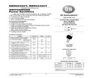
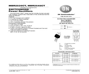
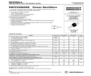
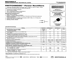
MBR2535CT/D SWITCHMODE Power Rectifiers MBR2535CT ... using the Schottky Barrier principle with a platinum barrier metal. These R2545CT stateoftheart devices have the following features: MB e Guardring for Stress Protection MBR2545CT is a e Low Forward Voltage Motorola Preferred Device e 150C Operating Junction Temperature e Guaranteed Reverse Avalanche SCHOTTKY BARRIER Mechanical Characteristics: RECTIFIERS Case: Epoxy, Molded 30 AMPERES Weight: 1.9 grams (approximately) 35 and 45 VOLTS e Finish: All External Surfaces Corrosion Resistant and Terminal Leads are Readily Solderable * Lead Temperature for Soldering Purposes: 260C Max. for 10 Seconds * Shipped 50 units per plastic tube e Marking: B2535, B2545 \ mp. | J 3 >} 2s CASE 221A-06 TO-220AB PLASTIC MAXIMUM RATINGS Rating Symbol MBR2535CT MBR2545CT Unit Peak Repetitive Reverse Voltage VRRM 35 45 Voits Working Peak Reverse Voltage VRWM DC Blocking Voltage VR Average Rectified Forward Current (Rated Vp) IF(AV) 30 30 Amps To = 130C Peak Repetitiv
 3 Pages, 195 KB, Scan


