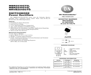
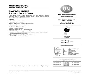
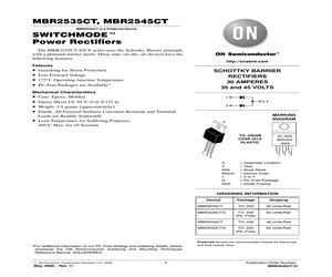
MBR2535CTG, MBR2545CTG Switchmode Power Rectifiers The MBR2535CTG/45CTG series uses the Schottky Barrier principle with a platinum barrier metal. These state-of-the-art devices have the following features: SCHOTTKY BARRIER RECTIFIERS 30 AMPERES 35 and 45 VOLTS Features * * * * http://onsemi.com Guardring for Stress Protection Low Forward Voltage 175C Operating Junction Temperature These are Pb-Free Devices* 1 2, 4 Mechanical Characteristics * * * * * 3 Case: Epoxy, Molded Epoxy Meets UL 94 V-0 @ 0.125 in Weight: 1.9 Grams (Approximately) Finish: All External Surfaces Corrosion Resistant and Terminal Leads are Readily Solderable Lead Temperature for Soldering Purposes: 260C Max. for 10 Seconds 4 1 2 3 TO-220 CASE 221A STYLE 6 MARKING DIAGRAM AY WW B25x5G AKA A Y WW B25x5 x G AKA = Assembly Location = Year = Work Week = Device Code = 3 or 4 = Pb-Free Package = Diode Polarity ORDERING INFORMATION Device Package Shipping MBR2535CTG TO-220 (Pb-Free) 50 Units/Rail MBR2545CTG T
 4 Pages, 85 KB, Original
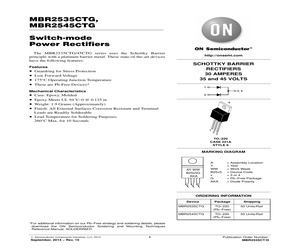
MBR2535CTG, MBR2545CTG, NRVB2545CTG SWITCHMODE Power Rectifiers The MBR2535CTG/45CTG series uses the Schottky Barrier principle with a platinum barrier metal. These state-of-the-art devices have the following features: Features Guardring for Stress Protection Low Forward Voltage 175C Operating Junction Temperature AEC-Q101 Qualified and PPAP Capable NRVB Prefix for Automotive and Other Applications Requiring Unique Site and Control Change Requirements These are Pb-Free Devices* http://onsemi.com SCHOTTKY BARRIER RECTIFIERS 30 AMPERES 35 and 45 VOLTS Mechanical Characteristics Case: Epoxy, Molded Epoxy Meets UL 94 V-0 @ 0.125 in Weight: 1.9 grams (approximately) Finish: All External Surfaces Corrosion Resistant and Terminal Leads are Readily Solderable Lead Temperature for Soldering Purposes: 260C Max. for 10 Seconds TO-220AB CASE 221A 1 2, 4 3 MARKING DIAGRAM AY WW B25x5G AKA A Y WW B25x5 x G AKA = Assembly Location = Year = Work Week = Device Code = 3 or 4 = Pb-Free Package = Diode
 4 Pages, 123 KB, Original
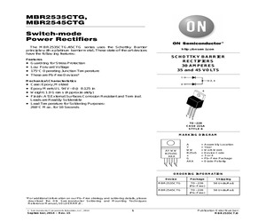
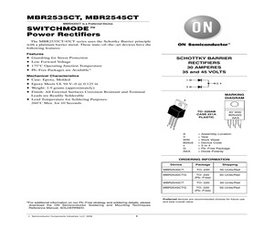
MBR2535CTG, MBR2545CTG Switchmode Power Rectifiers The MBR2535CTG/45CTG series uses the Schottky Barrier principle with a platinum barrier metal. These state-of-the-art devices have the following features: SCHOTTKY BARRIER RECTIFIERS 30 AMPERES 35 and 45 VOLTS Features * * * * http://onsemi.com Guardring for Stress Protection Low Forward Voltage 175C Operating Junction Temperature These are Pb-Free Devices* 1 2, 4 Mechanical Characteristics * * * * * 3 Case: Epoxy, Molded Epoxy Meets UL 94 V-0 @ 0.125 in Weight: 1.9 Grams (Approximately) Finish: All External Surfaces Corrosion Resistant and Terminal Leads are Readily Solderable Lead Temperature for Soldering Purposes: 260C Max. for 10 Seconds 4 1 2 3 TO-220 CASE 221A STYLE 6 MARKING DIAGRAM AY WW B25x5G AKA A Y WW B25x5 x G AKA = Assembly Location = Year = Work Week = Device Code = 3 or 4 = Pb-Free Package = Diode Polarity ORDERING INFORMATION Device Package Shipping MBR2535CTG TO-220 (Pb-Free) 50 Units/Rail MBR2545CTG T
 5 Pages, 229 KB, Original
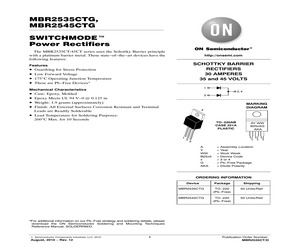
MBR2535CTG, MBR2545CTG Switchmode Power Rectifiers The MBR2535CTG/45CTG series uses the Schottky Barrier principle with a platinum barrier metal. These state-of-the-art devices have the following features: SCHOTTKY BARRIER RECTIFIERS 30 AMPERES 35 and 45 VOLTS Features * * * * http://onsemi.com Guardring for Stress Protection Low Forward Voltage 175C Operating Junction Temperature These are Pb-Free Devices* 1 2, 4 Mechanical Characteristics * * * * * 3 Case: Epoxy, Molded Epoxy Meets UL 94 V-0 @ 0.125 in Weight: 1.9 Grams (Approximately) Finish: All External Surfaces Corrosion Resistant and Terminal Leads are Readily Solderable Lead Temperature for Soldering Purposes: 260C Max. for 10 Seconds 4 1 2 3 TO-220 CASE 221A STYLE 6 MARKING DIAGRAM AY WW B25x5G AKA A Y WW B25x5 x G AKA = Assembly Location = Year = Work Week = Device Code = 3 or 4 = Pb-Free Package = Diode Polarity ORDERING INFORMATION Device Package Shipping MBR2535CTG TO-220 (Pb-Free) 50 Units/Rail MBR2545CTG T
 5 Pages, 86 KB, Original
MBR2535CTG, MBR2545CTG SWITCHMODE] Power Rectifiers The MBR2535CT/45CT series uses the Schottky Barrier principle with a platinum barrier metal. These state-of-the-art devices have the following features: http://onsemi.com SCHOTTKY BARRIER RECTIFIERS 30 AMPERES 35 and 45 VOLTS Features * * * * Guardring for Stress Protection Low Forward Voltage 175C Operating Junction Temperature These are Pb-Free Devices* 1 Mechanical Characteristics * * * * * 2, 4 Case: Epoxy, Molded Epoxy Meets UL 94 V-0 @ 0.125 in Weight: 1.9 grams (approximately) Finish: All External Surfaces Corrosion Resistant and Terminal Leads are Readily Solderable Lead Temperature for Soldering Purposes: 260C Max. for 10 Seconds 3 MARKING DIAGRAM 4 TO-220AB CASE 221A PLASTIC 1 2 AY WW B25x5G AKA 3 A Y WW B25x5 x G AKA = Assembly Location = Year = Work Week = Device Code = 3 or 4 = Pb-Free Package = Diode Polarity ORDERING INFORMATION Device Package Shipping MBR2535CTG TO-220 (Pb-Free) 50 Units/Rail MBR2545CTG TO-220 (Pb-Fr
 4 Pages, 93 KB, Original
MBR2535CTG, MBR2545CTG SWITCHMODE Power Rectifiers The MBR2535CTG/45CTG series uses the Schottky Barrier principle with a platinum barrier metal. These state-of-the-art devices have the following features: SCHOTTKY BARRIER RECTIFIERS 30 AMPERES 35 and 45 VOLTS Features * * * * http://onsemi.com Guardring for Stress Protection Low Forward Voltage 175C Operating Junction Temperature These are Pb-Free Devices* Mechanical Characteristics * * * * * Case: Epoxy, Molded Epoxy Meets UL 94 V-0 @ 0.125 in Weight: 1.9 grams (approximately) Finish: All External Surfaces Corrosion Resistant and Terminal Leads are Readily Solderable Lead Temperature for Soldering Purposes: 260C Max. for 10 Seconds TO-220AB CASE 221A 1 2, 4 3 MARKING DIAGRAM AY WW B25x5G AKA A Y WW B25x5 x G AKA = Assembly Location = Year = Work Week = Device Code = 3 or 4 = Pb-Free Package = Diode Polarity ORDERING INFORMATION Device *For additional information on our Pb-Free strategy and soldering details, please download the ON
 4 Pages, 90 KB, Original
16 20 20 20 20 20 20 20 20 20 17 180 180 200 260 190 180 150 150 150 150 150 150 150 150 150 150 150 250 Package Dimensions 1 2,4 3 STYLE 4 1 2 3 Package Leshan Radio Company, Ltd. http//:www.lrc.cn 16.1 Plastic-Sealed TO-220AB Schottky Rectifiers Device LMBR2535CTG LMBR2535CTLG LMBR2545CTG LMBR3045STG LMBR30H100CTG LMBR30H60CTG LMBR4015CTLG LMBR40250TG LMBR40L45CTG LMBR41H100CTG LMBR60H100CTG LMBR60L45CTG VRRM Min(V) VF IRM IO(rec) IFSM Max(A) Max(V) Max(mA) Max(A) 35 35 45 45 100 60 15 250 45 100 100 45 0.82 0.47 0.82 0.76 0.93 0.78 0.54 0.97 0.63 0.9 0.98 0.73 200 5000 20 200 4.5 300 10000 30 1200 10 10 1200 30 25 30 30 30 30 40 40 40 40 60 60 150 150 150 150 250 260 150 150 200 350 350 200 Package Dimensions 1 2,4 3 STYLE 4 1 2 3 Package 17. Plastic-Sealed TO-220FP Schottky Rectifiers Device LMBRF10H150CTG LMBRF20H150CTG LMBRF20L45CTG LMBRF30H150CTG LMBRF30L45CTG LMBRF20100CTG LMBRF20200CTG LMBRF2060CTG LMBRF20H100CTG LMBRF2545CTG LMBRF30H60CTG LMBRF40250TG VRRM Min(V) VF IRM IO(rec) IFSM Max
 225 Pages, 6963 KB, Original
RG MBRA160T3G MBRB1545CTT4G MBRB20200CTT4G MBRB2515LG MBRB2545CTT4G MBRD340G MBRD340T4G MBRD360T4G MBRD620CTT4G MBRD835LG MBRM120ET1G MBRM130LT1G MBRM130LT3G MBRS120T3G MBRS1540T3G MBRS260T3G MBRS3200T3 MBR0540T3G MBR1060G MBR130T1G MBR1535CTG MBR16100CTG MBR2535CTG MBR2545CTG MBR735G MCH12140DR2G MCR100-3RLG MC10ELT20DR2G MC10ELT21DG MC10ELT22DG MC10EL04DG MC10EL07DG MC10EL11DG MC10EL31DG MC10EL32DG MC10EL33DG MC10EL51DG MC10EL52DG MC10EL58DG MC10EL89DR2G MC10EP11DR2G MC10EP32DG MC10EP57DTR2G MC10H124PG MC100ELT20DR2G MC100ELT21DR2G MC100ELT22DG MC100ELT23DG MC100EL04DG MC100EL13DWG MC100EL17DWR2G MC100EL33DG MC100EL35DG MC100EL56DWG MC100EP11DR2G MC100EP17DWR2G MC100EP57DTR2G MC100LVELT23DR2G MC100LVEL14DWG MC100LVEL14DWR2G MC100LVEL16DG MC100LVEL16DR2G MC100LVEL17DWR2G MC100LVEL29DWG MC100LVEL91DWR2G MC100LVEL92DWR2G MC100LVEP111FAG MC100LVEP16DG MC100LVEP210FARG MC100LVE164FAG MC100LVE164FAR2G MC14052BCPG MC14052BDR2G MC14053BDR2G MC14066BDR2G MC1413DG MC1455BP1G MC1488PG MC1489APG MC1489PG M
 260 Pages, 833 KB, Original
89 --71J5254 1.58 1.51 ND3% BASE1 XXXX1861-0337-1-P 337 TSQ: 3001 CMS: CMS-USM TS host OP: NN COMP: 15-07-11 Hour: 11:45 TS:TS date TS time DISCRETES, VARISTORS & RF Find the Newest Technologies Online SCHOTTKY RECTIFIERS Tape Cut Mfg. Part No. MBR2515LG* MBR2535CTG* MBR2535CTLG* MBR2545CTG* MBR3045PTG* MBR3045WTG* MBR40250G* MBR40250TG* MBR6045WTG* MBR735G* MBR745G* Vrrm (V) 15 35 35 45 45 45 250 250 45 35 45 If(AV) (A) 25 30 25 30 30 30 40 40 60 7.5 7.5 VF (V) 380 0.72 0.47 0.82 0.76 720 970 970 750 840 840 Ifsm (mA) 150 150 150 150 200 200 150 150 500 150 150 Package TO-220AC TO-220 TO-220 TO-220 SOT-93 TO-247 TO-220AC TO-220AB TO-247 TO-220AC TO-220AC Stock No. 71J5256 98H0604 45J0803 98H0605 71J5257 71J5258 42K0020 42K0021 71J5260 98H0606 45J0808 1 SCHOTTKY DIODES--DISCRETE MBR SERIES SCHOTTKY RECTIFIERS (CONT.) Price Each 1-24 2.89 1.93 1.83 1.44 1.70 1.51 1.20 0.88 3.08 --3.87 2.76 2.16 1.94 2.16 1.85 5.55 5.18 0.79 0.49 0.74 0.52 15V (116797) Mfg. Part No. VS-10BQ015TRPBF VS-19TQ015PBF VS
 375 Pages, 58008 KB, Original
1.29 50 MBR2080CT A REC T0220 20A 80V SHTKY 2 50 1.29 50 MBR2090CT A REC T0220 20A 90V SHTKY 2 50 1.29 50 MBR2090CTLFAJ A REC T0220 20A 90V SHTKY 1 50 1.47 50 MBR2515L A REC T0220 25A 15V SHTKY 2 50 1.53 50 MBR2535CT A REC T0220 30A 35V SHTKY 2 50 1.20 50 MBR2535CTG A REC T0220 30A 35V SHTKY 2 50 1.20 50 MBR2535CTL A REC T0220 30A 35V SHTKY 2 50 1.20 50 MBR2535CTLG A REC T0220 30A 35V SHTKY 2 50 1.20 50 MBR2545CT A REC T0220 30A 45V SHTKY 2 50 1.20 50 MBR2545CTG A REC T0220 30A 45V SHTKY 2 50 1.20 50 MBR3045PT A REC T0218 30A 45V SHTKY 2 30 1.33 30 MBR3045WT A REC T0247 30A 45V SHTKY 1 30 1.67 30 MBR3100 A REC SURM 3A 100V SHTKY 2 500 .373 500 MBR3100RL A REC SURM 3A 100V SHTKY TR 2 1500 .373 1500 MBR340 A REC SURM 3A 40V SHTKY 2 500 .20 500 MBR340RL A REC SURM 3A 40V SHTKY TR 2 1500 .20 1500 MBR350RL A REC SURM 3A 50V SHTKY TR 2 1500 .20 1500 MBR360 A REC SURM 3A 60V SHTKY 2 500 .20 500 MBR360RL A REC SURM 3A 60V SHTKY TR 2 1500 .20 1500 MBR4015CTL A REC T0220 40A 15V SHTKY 2 50 .92 50 MBR4015LW
 296 Pages, 947 KB, Original
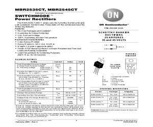
0C Max. for 10 Seconds 1 2, 4 3 MARKING DIAGRAM 4 TO-220AB CASE 221A PLASTIC 1 2 AY WW B25x5G AKA 3 A Y WW B25x5 x G AKA = Assembly Location = Year = Work Week = Device Code = 3 or 4 = Pb-Free Package = Diode Polarity ORDERING INFORMATION Device MBR2535CT MBR2535CTG MBR2545CT MBR2545CTG *For additional information on our Pb-Free strategy and soldering details, please download the ON Semiconductor Soldering and Mounting Techniques Reference Manual, SOLDERRM/D. (c) Semiconductor Components Industries, LLC, 2008 May, 2008 - Rev. 11 1 Package Shipping TO-220 50 Units/Rail TO-220 (Pb-Free) 50 Units/Rail TO-220 50 Units/Rail TO-220 (Pb-Free) 50 Units/Rail Preferred devices are recommended choices for future use and best overall value. Publication Order Number: MBR2535CT/D MBR2535CT, MBR2545CT MAXIMUM RATINGS Rating Symbol Peak Repetitive Reverse Voltage Working Peak Reverse Voltage DC Blocking Voltage MBR2535CT MBR2545CT Value VRRM VRWM VR Average Rectified Forward Current (Rated VR, TC = 160C) Unit V
 4 Pages, 117 KB, Original
0C Max. for 10 Seconds 1 2, 4 3 MARKING DIAGRAM 4 TO-220AB CASE 221A PLASTIC 1 2 AY WW B25x5G AKA 3 A Y WW B25x5 x G AKA = Assembly Location = Year = Work Week = Device Code = 3 or 4 = Pb-Free Package = Diode Polarity ORDERING INFORMATION Device MBR2535CT MBR2535CTG MBR2545CT MBR2545CTG *For additional information on our Pb-Free strategy and soldering details, please download the ON Semiconductor Soldering and Mounting Techniques Reference Manual, SOLDERRM/D. (c) Semiconductor Components Industries, LLC, 2008 1 Package Shipping TO-220 50 Units/Rail TO-220 (Pb-Free) 50 Units/Rail TO-220 50 Units/Rail TO-220 (Pb-Free) 50 Units/Rail Preferred devices are recommended choices for future use and best overall value. MBR2535CT, MBR2545CT MAXIMUM RATINGS Rating Symbol Peak Repetitive Reverse Voltage Working Peak Reverse Voltage DC Blocking Voltage MBR2535CT MBR2545CT Value VRRM VRWM VR Average Rectified Forward Current (Rated VR, TC = 160C) Unit V 35 45 IF(AV) 30 A Peak Repetitive Forward Current, per Dio
 3 Pages, 105 KB, Original
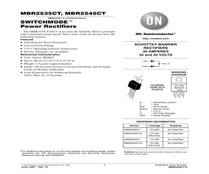
poses: MARKING DIAGRAM 260C Max. for 10 Seconds 4 TO-220AB CASE 221A PLASTIC 1 2 AY WW B25x5G AKA 3 A Y WW B25x5 x G AKA = Assembly Location = Year = Work Week = Device Code = 3 or 4 = Pb-Free Package = Diode Polarity ORDERING INFORMATION Device MBR2535CT MBR2535CTG MBR2545CT MBR2545CTG *For additional information on our Pb-Free strategy and soldering details, please download the ON Semiconductor Soldering and Mounting Techniques Reference Manual, SOLDERRM/D. (c) Semiconductor Components Industries, LLC, 2007 June, 2007 - Rev. 10 1 Package Shipping TO-220 50 Units/Rail TO-220 (Pb-Free) 50 Units/Rail TO-220 50 Units/Rail TO-220 (Pb-Free) 50 Units/Rail Preferred devices are recommended choices for future use and best overall value. Publication Order Number: MBR2535CT/D MBR2535CT, MBR2545CT MAXIMUM RATINGS Rating Symbol Peak Repetitive Reverse Voltage Working Peak Reverse Voltage DC Blocking Voltage MBR2535CT MBR2545CT Value VRRM VRWM VR Average Rectified Forward Current (Rated VR, TC = 160C) Unit V
 4 Pages, 74 KB, Original
MBRM130LT1G 863-MBRB4030G 863-1N5818G 863-MBR7030WTG 863-MBR2030CTLG 863-MMBD330T1G 863-MBRD330T4G 863-MBRS130T3G 863-MBRB3030CTG 863-MBRD330G 863-MBRD330RLG 863-MBRD630CTT4G 863-MBR735G 863-MBR2535CTLG 863-MBRB2535CTLT4G 863-MBRD1035CTLG 863-MBR1635G 863-MBR2535CTG 863-MBR1035G 863-MBR1535CTG 863-BAS40-04LT1G 863-BAS40-06LT1G 863-BAS40LT1G 863-NSR05F40NXT5G 863-NSR0340P2T5G 863-MBRS240LT3G 863-MBRA340T3G 863-NSR10F40NXT5G 863-MBRS540T3G 863-SS24T3G 863-MBRS2040LT3G 863-MBRS340T3G 863-MBR0540T1G 863-1N5822G 863-1N5822RLG 863-MBRS1540T3G 863-MBR140SFT1G 863-MBR140SFT3G 863-MBRA140T3G 863-MBRM140T1G 863-MBR340G 863-MBR340RLG 863-1N5819G 863-MBRS140T3G 863-NRVTS1045EMFST1G 863-NTS1045MFST1G 863-NTS1245MFST1G 863-NTS1545MFST1G 863-NRVTS1245EMFST1G SOD-123 SOD-123 SOD123 SOT-363 SOT-23 SOD-123 SOD-123 SOD-123 DSN-2 SMB SOD-523 DO-201AD DO-201AD SMC Powermite D2PAK DO-41 TO-247 TO-220 3 SC-70 DPAK 4 SMB D2PAK DPAK DPAK DPAK TO-220 TO-220 D2PAK 3 DPAK 4 TO-220 TO-220 TO-220 TO-220 SOT-23 SOT-23 SOT-23 D
 1 Pages, 253 KB, Original
V/s ESD Ratings: Machine Model = C Human Body Model = 3B ESD V TO-220AB CASE 221A PLASTIC 35 45 1 2 AY WW B25x5 A K A 3 A Y WW B25x5 x AKA = Assembly Location = Year = Work Week = Device Code = 3 or 4 = Diode Polarity ORDERING INFORMATION Device MBR2535CT MBR2535CTG Package Shipping TO-220 50 Units/Rail TO-220 (Pb-Free) 50 Units/Rail TO-220 50 Units/Rail TO-220 (Pb-Free) 50 Units/Rail V MBR2545CT >400 >8000 Maximum ratings are those values beyond which device damage can occur. Maximum ratings applied to the device are individual stress limit values (not normal operating conditions) and are not valid simultaneously. If these limits are exceeded, device functional operation is not implied, damage may occur and reliability may be affected. MBR2545CTG Preferred devices are recommended choices for future use and best overall value. *For additional information on our Pb-Free strategy and soldering details, please download the ON Semiconductor Soldering and Mounting Techniques Reference Manual, SOLDERRM
 4 Pages, 57 KB, Original


