7 1N5818 1N5819 1N5820 1N5821 1N5822 MBRP20030CTL MBRP20030CTL MBRP20030CTL MBRP20045CT MBRP20045CT MBRP20030CTL MBRP20030CTL MBRP20030CTL MBRP20045CT MBRP20045CT MBRP20060CT MBRP20060CT MBR2030CTL MBR2030CTL MBR2045CT MBR2045CT 1N5821 1N5822 MBRP20030CTL MBR2535CTL MBRB2535CTL MBR2545CT MBRB2545CT MBR2545CT MBRB2545CT MBR3045PT Page 454 454 454 454 447 452 452 447 452 452 447 452 452 447 350 350 350 350 350 350 350 350 350 350 146 146 146 159 159 159 252 252 252 262 262 252 252 252 262 262 270 270 180 180 184 184 159 159 252 195 127 198 130 198 130 232 AAAAAA AAAAA AAAAAA AAAAAAAA AAAAAA AAAAAA AA AAAAAA AAAAA AAAAAA AAA AAAAA AAAAAA AAAAAA AA AAAAAA AAAAA AAAAAA AAA AAAAAA AAAAAA AAAAAA AAAAA AAAAAA AAAAAAAA AAAAA AAAAAA AAAAAAAA AA Industry Part Number 28CPQ040 301CNQ040 301CNQ045 301CNQ050 30BF20 30BF40 30BF60 30BQ015 30BQ040 30BQ060 30CPQ035 30CPQ040 30CPQ045 30CPQ050 30CTQ030 30CTQ035 30CTQ035S 30CTQ040 30CTQ040S 30CTQ045 30CTQ045S 30CTQ050 30CTQ050S 30DL1 30DL2 30WQ03FN 30WQ04FN 30WQ06FN 3
 57 Pages, 636 KB, Original
7 1N5818 1N5819 1N5820 1N5821 1N5822 MBRP20030CTL MBRP20030CTL MBRP20030CTL MBRP20045CT MBRP20045CT MBRP20030CTL MBRP20030CTL MBRP20030CTL MBRP20045CT MBRP20045CT MBRP20060CT MBRP20060CT MBR2030CTL MBR2030CTL MBR2045CT MBR2045CT 1N5821 1N5822 MBRP20030CTL MBR2535CTL MBRB2535CTL MBR2545CT MBRB2545CT MBR2545CT MBRB2545CT MBR3045PT Page 454 454 454 454 447 452 452 447 452 452 447 452 452 447 350 350 350 350 350 350 350 350 350 350 146 146 146 159 159 159 252 252 252 262 262 252 252 252 262 262 270 270 180 180 184 184 159 159 252 195 127 198 130 198 130 232 AAAAAA AAAAA AAAAAA AAAAAAAA AAAAAA AAAAAA AA AAAAAA AAAAA AAAAAA AAA AAAAA AAAAAA AAAAAA AA AAAAAA AAAAA AAAAAA AAA AAAAAA AAAAAA AAAAAA AAAAA AAAAAA AAAAAAAA AAAAA AAAAAA AAAAAAAA AA Industry Part Number 28CPQ040 301CNQ040 301CNQ045 301CNQ050 30BF20 30BF40 30BF60 30BQ015 30BQ040 30BQ060 30CPQ035 30CPQ040 30CPQ045 30CPQ050 30CTQ030 30CTQ035 30CTQ035S 30CTQ040 30CTQ040S 30CTQ045 30CTQ045S 30CTQ050 30CTQ050S 30DL1 30DL2 30WQ03FN 30WQ04FN 30WQ06FN 3
 57 Pages, 597 KB, Original
7 1N5818 1N5819 1N5820 1N5821 1N5822 MBRP20030CTL MBRP20030CTL MBRP20030CTL MBRP20045CT MBRP20045CT MBRP20030CTL MBRP20030CTL MBRP20030CTL MBRP20045CT MBRP20045CT MBRP20060CT MBRP20060CT MBR2030CTL MBR2030CTL MBR2045CT MBR2045CT 1N5821 1N5822 MBRP20030CTL MBR2535CTL MBRB2535CTL MBRB2545CT MBRB2545CT MBR3045PT MBR3045PT MBRP30045CT Page 519 519 519 519 512 514 514 512 514 514 512 514 514 512 434 434 434 434 434 434 434 434 434 434 203 203 203 220 220 220 308 308 308 318 318 308 308 308 318 318 326 326 241 241 245 245 220 220 308 256 184 187 187 290 290 321 AAAAAA AAAAA AAAAAA AAAAAAAA AAAAAA AAAAAA AA AAAAAA AAAAA AAAAAA AAAAAAAA AAAAA AAAAAA AAAAAAAA AAAAAA AAAAA AAAAAA AAA AAAAAA AAAAAA AA AAAAAA AAAAA AAAAAA AAAAAAAA AAAAAA AAAAAAAA Industry Part Number 301CNQ045 301CNQ050 30BF20 30BF40 30BF60 30BQ015 30BQ040 30BQ060 30CPQ035 30CPQ040 30CPQ045 30CPQ050 30CTQ035 30CTQ035S 30CTQ040S 30CTQ045S 30CTQ050S 30DL1 30DL2 30WQ03FN 30WQ04FN 30WQ06FN 31DQ03 31DQ04 31DQ05 31DQ06 31DQ09 31DQ10 32CTQ030 32CTQ
 17 Pages, 142 KB, Original
7 1N5818 1N5819 1N5820 1N5821 1N5822 MBRP20030CTL MBRP20030CTL MBRP20030CTL MBRP20045CT MBRP20045CT MBRP20030CTL MBRP20030CTL MBRP20030CTL MBRP20045CT MBRP20045CT MBRP20060CT MBRP20060CT MBR2030CTL MBR2030CTL MBR2045CT MBR2045CT 1N5821 1N5822 MBRP20030CTL MBR2535CTL MBRB2535CTL MBR2545CT MBRB2545CT MBR2545CT MBRB2545CT MBR3045PT Page 454 454 454 454 447 452 452 447 452 452 447 452 452 447 350 350 350 350 350 350 350 350 350 350 146 146 146 159 159 159 252 252 252 262 262 252 252 252 262 262 270 270 180 180 184 184 159 159 252 195 127 198 130 198 130 232 AAAAAA AAAAA AAAAAA AAAAAAAA AAAAAA AAAAAA AA AAAAAA AAAAA AAAAAA AAA AAAAA AAAAAA AAAAAA AA AAAAAA AAAAA AAAAAA AAA AAAAAA AAAAAA AAAAAA AAAAA AAAAAA AAAAAAAA AAAAA AAAAAA AAAAAAAA AA Industry Part Number 28CPQ040 301CNQ040 301CNQ045 301CNQ050 30BF20 30BF40 30BF60 30BQ015 30BQ040 30BQ060 30CPQ035 30CPQ040 30CPQ045 30CPQ050 30CTQ030 30CTQ035 30CTQ035S 30CTQ040 30CTQ040S 30CTQ045 30CTQ045S 30CTQ050 30CTQ050S 30DL1 30DL2 30WQ03FN 30WQ04FN 30WQ06FN 3
 57 Pages, 601 KB, Original
7 1N5818 1N5819 1N5820 1N5821 1N5822 MBRP20030CTL MBRP20030CTL MBRP20030CTL MBRP20045CT MBRP20045CT MBRP20030CTL MBRP20030CTL MBRP20030CTL MBRP20045CT MBRP20045CT MBRP20060CT MBRP20060CT MBR2030CTL MBR2030CTL MBR2045CT MBR2045CT 1N5821 1N5822 MBRP20030CTL MBR2535CTL MBRB2535CTL MBR2545CT MBRB2545CT MBR2545CT MBRB2545CT MBR3045PT Page 454 454 454 454 447 452 452 447 452 452 447 452 452 447 350 350 350 350 350 350 350 350 350 350 146 146 146 159 159 159 252 252 252 262 262 252 252 252 262 262 270 270 180 180 184 184 159 159 252 195 127 198 130 198 130 232 AAAAAA AAAAA AAAAAA AAAAAAAA AAAAAA AAAAAA AA AAAAAA AAAAA AAAAAA AAA AAAAA AAAAAA AAAAAA AA AAAAAA AAAAA AAAAAA AAA AAAAAA AAAAAA AAAAAA AAAAA AAAAAA AAAAAAAA AAAAA AAAAAA AAAAAAAA AA Industry Part Number 28CPQ040 301CNQ040 301CNQ045 301CNQ050 30BF20 30BF40 30BF60 30BQ015 30BQ040 30BQ060 30CPQ035 30CPQ040 30CPQ045 30CPQ050 30CTQ030 30CTQ035 30CTQ035S 30CTQ040 30CTQ040S 30CTQ045 30CTQ045S 30CTQ050 30CTQ050S 30DL1 30DL2 30WQ03FN 30WQ04FN 30WQ06FN 3
 57 Pages, 612 KB, Original
7 1N5818 1N5819 1N5820 1N5821 1N5822 MBRP20030CTL MBRP20030CTL MBRP20030CTL MBRP20045CT MBRP20045CT MBRP20030CTL MBRP20030CTL MBRP20030CTL MBRP20045CT MBRP20045CT MBRP20060CT MBRP20060CT MBR2030CTL MBR2030CTL MBR2045CT MBR2045CT 1N5821 1N5822 MBRP20030CTL MBR2535CTL MBRB2535CTL MBR2545CT MBRB2545CT MBR2545CT MBRB2545CT MBR3045PT Page 454 454 454 454 447 452 452 447 452 452 447 452 452 447 350 350 350 350 350 350 350 350 350 350 146 146 146 159 159 159 252 252 252 262 262 252 252 252 262 262 270 270 180 180 184 184 159 159 252 195 127 198 130 198 130 232 AAAAAA AAAAA AAAAAA AAAAAAAA AAAAAA AAAAAA AA AAAAAA AAAAA AAAAAA AAA AAAAA AAAAAA AAAAAA AA AAAAAA AAAAA AAAAAA AAA AAAAAA AAAAAA AAAAAA AAAAA AAAAAA AAAAAAAA AAAAA AAAAAA AAAAAAAA AA Industry Part Number 28CPQ040 301CNQ040 301CNQ045 301CNQ050 30BF20 30BF40 30BF60 30BQ015 30BQ040 30BQ060 30CPQ035 30CPQ040 30CPQ045 30CPQ050 30CTQ030 30CTQ035 30CTQ035S 30CTQ040 30CTQ040S 30CTQ045 30CTQ045S 30CTQ050 30CTQ050S 30DL1 30DL2 30WQ03FN 30WQ04FN 30WQ06FN 3
 57 Pages, 608 KB, Original
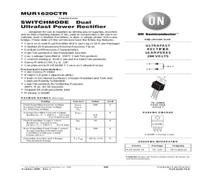
 . . . . . 152 16 Amp, 100 Volt SWITCHMODE Power Rectifier . . . . . . . . . . . . . . . . . . . . . . . . . . . . . 177 http://onsemi.com 6 Device MBR1635 MBR1645 MBR20100CT MBR20200CT MBR2030CTL MBR2045CT MBR2060CT MBR2080CT MBR2090CT MBR2515L MBR2535CT MBR2535CTL MBR2545CT MBR3045PT MBR3045ST MBR3045WT MBR3100 MBR340 MBR350 MBR360 MBR4015LWT MBR4045PT MBR4045WT MBR5025L MBR6045PT MBR6045WT MBR735 MBR745 MBRA130LT3 MBRA140T3 MBRB1045 MBRB1545CT MBRB20100CT MBRB20200CT MBRB2060CT MBRB2515L MBRB2535CTL MBRB2545CT MBRB3030CT MBRB3030CTL MBRB4030 MBRD1035CTL MBRD320 MBRD330 MBRD340 MBRD350 Function Page 16 Amp, 35 Volt SWITCHMODE Power Rectifier . . . . . . . . . . . . . . . . . . . . . . . . . . . . . . 215 16 Amp, 45 Volt SWITCHMODE Power Rectifier . . . . . . . . . . . . . . . . . . . . . . . . . . . . . . 215 20 Amp, 100 Volt SWITCHMODE Power Rectifier . . . . . . . . . . . . . . . . . . . . . . . . . . . . . 189 20 Amp, 200 Volt SWITCHMODE Dual Schottky Power Rectifier . . . . . . . . . . . .
 578 Pages, 6112 KB, Original
7 1N5818 1N5819 1N5820 1N5821 1N5822 MBRP20030CTL MBRP20030CTL MBRP20030CTL MBRP20045CT MBRP20045CT MBRP20030CTL MBRP20030CTL MBRP20030CTL MBRP20045CT MBRP20045CT MBRP20060CT MBRP20060CT MBR2030CTL MBR2030CTL MBR2045CT MBR2045CT 1N5821 1N5822 MBRP20030CTL MBR2535CTL MBRB2535CTL MBR2545CT MBRB2545CT MBR2545CT MBRB2545CT MBR3045PT Page 454 454 454 454 447 452 452 447 452 452 447 452 452 447 350 350 350 350 350 350 350 350 350 350 146 146 146 159 159 159 252 252 252 262 262 252 252 252 262 262 270 270 180 180 184 184 159 159 252 195 127 198 130 198 130 232 AAAAAA AAAAA AAAAAA AAAAAAAA AAAAAA AAAAAA AA AAAAAA AAAAA AAAAAA AAA AAAAA AAAAAA AAAAAA AA AAAAAA AAAAA AAAAAA AAA AAAAAA AAAAAA AAAAAA AAAAA AAAAAA AAAAAAAA AAAAA AAAAAA AAAAAAAA AA Industry Part Number 28CPQ040 301CNQ040 301CNQ045 301CNQ050 30BF20 30BF40 30BF60 30BQ015 30BQ040 30BQ060 30CPQ035 30CPQ040 30CPQ045 30CPQ050 30CTQ030 30CTQ035 30CTQ035S 30CTQ040 30CTQ040S 30CTQ045 30CTQ045S 30CTQ050 30CTQ050S 30DL1 30DL2 30WQ03FN 30WQ04FN 30WQ06FN 3
 56 Pages, 587 KB, Original
7 1N5818 1N5819 1N5820 1N5821 1N5822 MBRP20030CTL MBRP20030CTL MBRP20030CTL MBRP20045CT MBRP20045CT MBRP20030CTL MBRP20030CTL MBRP20030CTL MBRP20045CT MBRP20045CT MBRP20060CT MBRP20060CT MBR2030CTL MBR2030CTL MBR2045CT MBR2045CT 1N5821 1N5822 MBRP20030CTL MBR2535CTL MBRB2535CTL MBR2545CT MBRB2545CT MBR2545CT MBRB2545CT MBR3045PT Page 454 454 454 454 447 452 452 447 452 452 447 452 452 447 350 350 350 350 350 350 350 350 350 350 146 146 146 159 159 159 252 252 252 262 262 252 252 252 262 262 270 270 180 180 184 184 159 159 252 195 127 198 130 198 130 232 AAAAAA AAAAA AAAAAA AAAAAAAA AAAAAA AAAAAA AA AAAAAA AAAAA AAAAAA AAA AAAAA AAAAAA AAAAAA AA AAAAAA AAAAA AAAAAA AAA AAAAAA AAAAAA AAAAAA AAAAA AAAAAA AAAAAAAA AAAAA AAAAAA AAAAAAAA AA Industry Part Number 28CPQ040 301CNQ040 301CNQ045 301CNQ050 30BF20 30BF40 30BF60 30BQ015 30BQ040 30BQ060 30CPQ035 30CPQ040 30CPQ045 30CPQ050 30CTQ030 30CTQ035 30CTQ035S 30CTQ040 30CTQ040S 30CTQ045 30CTQ045S 30CTQ050 30CTQ050S 30DL1 30DL2 30WQ03FN 30WQ04FN 30WQ06FN 3
 59 Pages, 641 KB, Original
7 1N5818 1N5819 1N5820 1N5821 1N5822 MBRP20030CTL MBRP20030CTL MBRP20030CTL MBRP20045CT MBRP20045CT MBRP20030CTL MBRP20030CTL MBRP20030CTL MBRP20045CT MBRP20045CT MBRP20060CT MBRP20060CT MBR2030CTL MBR2030CTL MBR2045CT MBR2045CT 1N5821 1N5822 MBRP20030CTL MBR2535CTL MBRB2535CTL MBR2545CT MBRB2545CT MBR2545CT MBRB2545CT MBR3045PT Page 454 454 454 454 447 452 452 447 452 452 447 452 452 447 350 350 350 350 350 350 350 350 350 350 146 146 146 159 159 159 252 252 252 262 262 252 252 252 262 262 270 270 180 180 184 184 159 159 252 195 127 198 130 198 130 232 AAAAAA AAAAA AAAAAA AAAAAAAA AAAAAA AAAAAA AA AAAAAA AAAAA AAAAAA AAA AAAAA AAAAAA AAAAAA AA AAAAAA AAAAA AAAAAA AAA AAAAAA AAAAAA AAAAAA AAAAA AAAAAA AAAAAAAA AAAAA AAAAAA AAAAAAAA AA Industry Part Number 28CPQ040 301CNQ040 301CNQ045 301CNQ050 30BF20 30BF40 30BF60 30BQ015 30BQ040 30BQ060 30CPQ035 30CPQ040 30CPQ045 30CPQ050 30CTQ030 30CTQ035 30CTQ035S 30CTQ040 30CTQ040S 30CTQ045 30CTQ045S 30CTQ050 30CTQ050S 30DL1 30DL2 30WQ03FN 30WQ04FN 30WQ06FN 3
 57 Pages, 608 KB, Original
7 1N5818 1N5819 1N5820 1N5821 1N5822 MBRP20030CTL MBRP20030CTL MBRP20030CTL MBRP20045CT MBRP20045CT MBRP20030CTL MBRP20030CTL MBRP20030CTL MBRP20045CT MBRP20045CT MBRP20060CT MBRP20060CT MBR2030CTL MBR2030CTL MBR2045CT MBR2045CT 1N5821 1N5822 MBRP20030CTL MBR2535CTL MBRB2535CTL MBR2545CT MBRB2545CT MBR2545CT MBRB2545CT MBR3045PT Page 454 454 454 454 447 452 452 447 452 452 447 452 452 447 350 350 350 350 350 350 350 350 350 350 146 146 146 159 159 159 252 252 252 262 262 252 252 252 262 262 270 270 180 180 184 184 159 159 252 195 127 198 130 198 130 232 AAAAAA AAAAA AAAAAA AAAAAAAA AAAAAA AAAAAA AA AAAAAA AAAAA AAAAAA AAA AAAAA AAAAAA AAAAAA AA AAAAAA AAAAA AAAAAA AAA AAAAAA AAAAAA AAAAAA AAAAA AAAAAA AAAAAAAA AAAAA AAAAAA AAAAAAAA AA Industry Part Number 28CPQ040 301CNQ040 301CNQ045 301CNQ050 30BF20 30BF40 30BF60 30BQ015 30BQ040 30BQ060 30CPQ035 30CPQ040 30CPQ045 30CPQ050 30CTQ030 30CTQ035 30CTQ035S 30CTQ040 30CTQ040S 30CTQ045 30CTQ045S 30CTQ050 30CTQ050S 30DL1 30DL2 30WQ03FN 30WQ04FN 30WQ06FN 3
 58 Pages, 610 KB, Original
7 1N5818 1N5819 1N5820 1N5821 1N5822 MBRP20030CTL MBRP20030CTL MBRP20030CTL MBRP20045CT MBRP20045CT MBRP20030CTL MBRP20030CTL MBRP20030CTL MBRP20045CT MBRP20045CT MBRP20060CT MBRP20060CT MBR2030CTL MBR2030CTL MBR2045CT MBR2045CT 1N5821 1N5822 MBRP20030CTL MBR2535CTL MBRB2535CTL MBR2545CT MBRB2545CT MBR2545CT MBRB2545CT MBR3045PT Page 454 454 454 454 447 452 452 447 452 452 447 452 452 447 350 350 350 350 350 350 350 350 350 350 146 146 146 159 159 159 252 252 252 262 262 252 252 252 262 262 270 270 180 180 184 184 159 159 252 195 127 198 130 198 130 232 AAAAAA AAAAA AAAAAA AAAAAAAA AAAAAA AAAAAA AA AAAAAA AAAAA AAAAAA AAA AAAAA AAAAAA AAAAAA AA AAAAAA AAAAA AAAAAA AAA AAAAAA AAAAAA AAAAAA AAAAA AAAAAA AAAAAAAA AAAAA AAAAAA AAAAAAAA AA Industry Part Number 28CPQ040 301CNQ040 301CNQ045 301CNQ050 30BF20 30BF40 30BF60 30BQ015 30BQ040 30BQ060 30CPQ035 30CPQ040 30CPQ045 30CPQ050 30CTQ030 30CTQ035 30CTQ035S 30CTQ040 30CTQ040S 30CTQ045 30CTQ045S 30CTQ050 30CTQ050S 30DL1 30DL2 30WQ03FN 30WQ04FN 30WQ06FN 3
 60 Pages, 640 KB, Original
7 1N5818 1N5819 1N5820 1N5821 1N5822 MBRP20030CTL MBRP20030CTL MBRP20030CTL MBRP20045CT MBRP20045CT MBRP20030CTL MBRP20030CTL MBRP20030CTL MBRP20045CT MBRP20045CT MBRP20060CT MBRP20060CT MBR2030CTL MBR2030CTL MBR2045CT MBR2045CT 1N5821 1N5822 MBRP20030CTL MBR2535CTL MBRB2535CTL MBR2545CT MBRB2545CT MBR2545CT MBRB2545CT MBR3045PT Page 454 454 454 454 447 452 452 447 452 452 447 452 452 447 350 350 350 350 350 350 350 350 350 350 146 146 146 159 159 159 252 252 252 262 262 252 252 252 262 262 270 270 180 180 184 184 159 159 252 195 127 198 130 198 130 232 AAAAAA AAAAA AAAAAA AAAAAAAA AAAAAA AAAAAA AA AAAAAA AAAAA AAAAAA AAA AAAAA AAAAAA AAAAAA AA AAAAAA AAAAA AAAAAA AAA AAAAAA AAAAAA AAAAAA AAAAA AAAAAA AAAAAAAA AAAAA AAAAAA AAAAAAAA AA Industry Part Number 28CPQ040 301CNQ040 301CNQ045 301CNQ050 30BF20 30BF40 30BF60 30BQ015 30BQ040 30BQ060 30CPQ035 30CPQ040 30CPQ045 30CPQ050 30CTQ030 30CTQ035 30CTQ035S 30CTQ040 30CTQ040S 30CTQ045 30CTQ045S 30CTQ050 30CTQ050S 30DL1 30DL2 30WQ03FN 30WQ04FN 30WQ06FN 3
 57 Pages, 592 KB, Original
7 1N5818 1N5819 1N5820 1N5821 1N5822 MBRP20030CTL MBRP20030CTL MBRP20030CTL MBRP20045CT MBRP20045CT MBRP20030CTL MBRP20030CTL MBRP20030CTL MBRP20045CT MBRP20045CT MBRP20060CT MBRP20060CT MBR2030CTL MBR2030CTL MBR2045CT MBR2045CT 1N5821 1N5822 MBRP20030CTL MBR2535CTL MBRB2535CTL MBR2545CT MBRB2545CT MBR2545CT MBRB2545CT MBR3045PT Page 454 454 454 454 447 452 452 447 452 452 447 452 452 447 350 350 350 350 350 350 350 350 350 350 146 146 146 159 159 159 252 252 252 262 262 252 252 252 262 262 270 270 180 180 184 184 159 159 252 195 127 198 130 198 130 232 AAAAAA AAAAA AAAAAA AAAAAAAA AAAAAA AAAAAA AA AAAAAA AAAAA AAAAAA AAA AAAAA AAAAAA AAAAAA AA AAAAAA AAAAA AAAAAA AAA AAAAAA AAAAAA AAAAAA AAAAA AAAAAA AAAAAAAA AAAAA AAAAAA AAAAAAAA AA Industry Part Number 28CPQ040 301CNQ040 301CNQ045 301CNQ050 30BF20 30BF40 30BF60 30BQ015 30BQ040 30BQ060 30CPQ035 30CPQ040 30CPQ045 30CPQ050 30CTQ030 30CTQ035 30CTQ035S 30CTQ040 30CTQ040S 30CTQ045 30CTQ045S 30CTQ050 30CTQ050S 30DL1 30DL2 30WQ03FN 30WQ04FN 30WQ06FN 3
 57 Pages, 609 KB, Original
7 1N5818 1N5819 1N5820 1N5821 1N5822 MBRP20030CTL MBRP20030CTL MBRP20030CTL MBRP20045CT MBRP20045CT MBRP20030CTL MBRP20030CTL MBRP20030CTL MBRP20045CT MBRP20045CT MBRP20060CT MBRP20060CT MBR2030CTL MBR2030CTL MBR2045CT MBR2045CT 1N5821 1N5822 MBRP20030CTL MBR2535CTL MBRB2535CTL MBR2545CT MBRB2545CT MBR2545CT MBRB2545CT MBR3045PT Page 454 454 454 454 447 452 452 447 452 452 447 452 452 447 350 350 350 350 350 350 350 350 350 350 146 146 146 159 159 159 252 252 252 262 262 252 252 252 262 262 270 270 180 180 184 184 159 159 252 195 127 198 130 198 130 232 AAAAAA AAAAA AAAAAA AAAAAAAA AAAAAA AAAAAA AA AAAAAA AAAAA AAAAAA AAA AAAAA AAAAAA AAAAAA AA AAAAAA AAAAA AAAAAA AAA AAAAAA AAAAAA AAAAAA AAAAA AAAAAA AAAAAAAA AAAAA AAAAAA AAAAAAAA AA Industry Part Number 28CPQ040 301CNQ040 301CNQ045 301CNQ050 30BF20 30BF40 30BF60 30BQ015 30BQ040 30BQ060 30CPQ035 30CPQ040 30CPQ045 30CPQ050 30CTQ030 30CTQ035 30CTQ035S 30CTQ040 30CTQ040S 30CTQ045 30CTQ045S 30CTQ050 30CTQ050S 30DL1 30DL2 30WQ03FN 30WQ04FN 30WQ06FN 3
 59 Pages, 641 KB, Original


