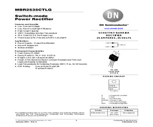
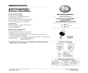
d the ON Semiconductor Soldering and Mounting Techniques Reference Manual, SOLDERRM/D. (c) Semiconductor Components Industries, LLC, 2015 January, 2015 - Rev. 6 1 Device Package Shipping MBR2535CTLG TO-220 (Pb-Free) 50 Units/Rail Publication Order Number: MBR2535CTL/D MBR2535CTLG MAXIMUM RATINGS (Per Leg) Symbol Value Unit Peak Repetitive Reverse Voltage Working Peak Reverse Voltage DC Blocking Voltage VRRM VRWM VR 35 V Average Rectified Forward Current (TC = 142C per Diode) (TC = 142C per Device) IF(AV) Peak Repetitive Forward Current, per Leg (Sq Wave, 20 kHz, TC = 139C) IFRM 25 A Non-Repetitive Peak Surge Current (Surge Applied at Rated Load Conditions, Halfwave, Single Phase, 60 Hz) IFSM 150 A Peak Repetitive Reverse Surge Current (2.0 ms, 1.0 kHz) IRRM 1.0 A Storage Temperature Range Tstg -65 to +150 C Operating Junction Temperature (Note 1) TJ -65 to +150 C Voltage Rate of Change (Rated VR) dv/dt 10,000 V/ms Controlled Avalanche Energy Waval 20 mJ Rating A 12.5 25 Stresses exceeding those l
 4 Pages, 75 KB, Original
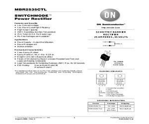
 Package AKA = Polarity Designator ORDERING INFORMATION Device MBR2535CTL MBR2535CTLG (c) Semiconductor Components Industries, LLC, 2006 August, 2006 - Rev. 4 1 Package Shipping TO-220 50 Units/Rail TO-220 (Pb-Free) 50 Units/Rail Publication Order Number: MBR2535CTL/D MBR2535CTL MAXIMUM RATINGS (Per Leg) Symbol Value Unit Peak Repetitive Reverse Voltage Working Peak Reverse Voltage DC Blocking Voltage VRRM VRWM VR 35 V Average Rectified Forward Current (TC = 142C per Diode) (TC = 142C per Device) IF(AV) Peak Repetitive Forward Current, per Leg (Sq Wave, 20 kHz, TC = 139C) IFRM 25 A Non-Repetitive Peak Surge Current (Surge Applied at Rated Load Conditions, Halfwave, Single Phase, 60 Hz) IFSM 150 A Peak Repetitive Reverse Surge Current (2.0 ms, 1.0 kHz) IRRM 1.0 A Storage Temperature Range Tstg -65 to +150 C Rating A 12.5 25 TJ -65 to +150 C Voltage Rate of Change (Rated VR) dv/dt 10,000 V/ms Controlled Avalanche Energy Waval 20 mJ Operating Junction Temperature (Note 1) Stresses exceeding Maximum
 4 Pages, 50 KB, Original
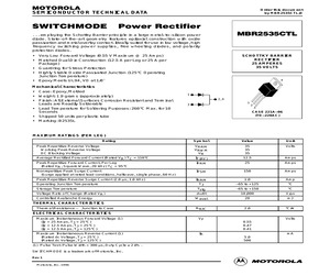
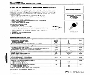
MBR2535CTL/D SEMICONDUCTOR TECHNICAL DATA . . . employing the Schottky Barrier principle in a large metal-to-silicon power diode. State-of-the-art geometry features epitaxial construction with oxide passivation and metal overlay contact. Ideally suited for use in low voltage, high frequency switching power supplies, free wheeling diodes, and polarity protection diodes. * Very Low Forward Voltage (0.55 V Maximum @ 25 Amps) * Matched Dual Die Construction (12.5 A per Leg or 25 A per Package) * Guardring for Stress Protection * Highly Stable Oxide Passivated Junction (125C Operating Junction Temperature) * Epoxy Meets UL94, VO at 1/8 SCHOTTKY BARRIER RECTIFIER 25 AMPERES 35 VOLTS 4 Mechanical Characteristics * Case: Epoxy, Molded * Weight: 1.9 grams (approximately) * Finish: All External Surfaces Corrosion Resistant and Terminal Leads are Readily Solderable * Lead Temperature for Soldering Purposes: 260C Max. for 10 Seconds * Shipped 50 units per plastic tube * Marking: B2535L 1 2, 4 1 3 2 3 CASE 22
 4 Pages, 51 KB, Original
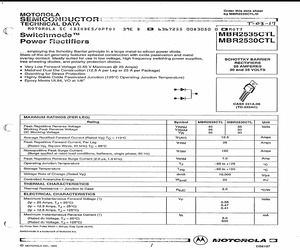
d Avalanche Energy Waval 20 mJ Rating Semiconductor Components Industries, LLC, 2000 October, 2000 - Rev. 2 1 TO-220AB CASE 221A PLASTIC MARKING DIAGRAM ORDERING INFORMATION Device MBR2535CTL Package Shipping TO-220 50 Units/Rail Publication Order Number: MBR2535CTL/D MBR2535CTL THERMAL CHARACTERISTICS Characteristic Thermal Resistance -- Junction to Case Symbol Max Unit RJC 2.0 C/W ELECTRICAL CHARACTERISTICS (Per Leg) Maximum Instantaneous Forward Voltage (Note 1.) (IF = 25 Amps, TJ = 25C) (IF = 12.5 Amps, TJ = 25C) (IF = 12.5 Amps, TJ = 125C) VF Maximum Instantaneous Reverse Current (Note 1.) (Rated dc Voltage, TJ = 25C) (Rated dc Voltage, TJ = 125C) IR Volts 0.55 0.47 0.41 mA 5.0 500 1. Pulse Test: Pulse Width = 300 s, Duty Cycle 2.0%. 50 IF, INSTANEOUS FORWARD CURRENT (AMP) 20 TJ = 125C 10 5 TJ = 25C 2 1 0.5 0.2 0.1 0 0.1 0.2 0.3 0.4 0.5 0.6 0.7 0.8 vF, INSTANTANEOUS VOLTAGE (VOLTS) Figure 1. Typical Forward Voltage, Per Leg http://onsemi.com 2 0.9 10 1000 TJ = 125C IR , REVERSE CURRENT (mA)
 4 Pages, 43 KB, Original
d the ON Semiconductor Soldering and Mounting Techniques Reference Manual, SOLDERRM/D. (c) Semiconductor Components Industries, LLC, 2015 January, 2015 - Rev. 6 1 Device Package Shipping MBR2535CTLG TO-220 (Pb-Free) 50 Units/Rail Publication Order Number: MBR2535CTL/D MBR2535CTLG MAXIMUM RATINGS (Per Leg) Symbol Value Unit Peak Repetitive Reverse Voltage Working Peak Reverse Voltage DC Blocking Voltage VRRM VRWM VR 35 V Average Rectified Forward Current (TC = 142C per Diode) (TC = 142C per Device) IF(AV) Peak Repetitive Forward Current, per Leg (Sq Wave, 20 kHz, TC = 139C) IFRM 25 A Non-Repetitive Peak Surge Current (Surge Applied at Rated Load Conditions, Halfwave, Single Phase, 60 Hz) IFSM 150 A Peak Repetitive Reverse Surge Current (2.0 ms, 1.0 kHz) IRRM 1.0 A Storage Temperature Range Tstg -65 to +150 C Operating Junction Temperature (Note 1) TJ -65 to +150 C Voltage Rate of Change (Rated VR) dv/dt 10,000 V/ms Controlled Avalanche Energy Waval 20 mJ Rating A 12.5 25 Stresses exceeding those l
 5 Pages, 76 KB, Original
ree Package AKA = Polarity Designator ORDERING INFORMATION Device MBR2535CTL MBR2535CTLG (c) Semiconductor Components Industries, LLC, 2008 May, 2008 - Rev. 5 1 Package Shipping TO-220 50 Units/Rail TO-220 (Pb-Free) 50 Units/Rail Publication Order Number: MBR2535CTL/D MBR2535CTL MAXIMUM RATINGS (Per Leg) Symbol Value Unit Peak Repetitive Reverse Voltage Working Peak Reverse Voltage DC Blocking Voltage Rating VRRM VRWM VR 35 V Average Rectified Forward Current (TC = 142C per Diode) (TC = 142C per Device) IF(AV) Peak Repetitive Forward Current, per Leg (Sq Wave, 20 kHz, TC = 139C) IFRM 25 A Non-Repetitive Peak Surge Current (Surge Applied at Rated Load Conditions, Halfwave, Single Phase, 60 Hz) IFSM 150 A Peak Repetitive Reverse Surge Current (2.0 ms, 1.0 kHz) IRRM 1.0 A Storage Temperature Range Tstg -65 to +150 C TJ -65 to +150 C dv/dt 10,000 V/ms Operating Junction Temperature (Note 1) Voltage Rate of Change (Rated VR) A 12.5 25 Controlled Avalanche Energy Waval 20 mJ Stresses exceeding Maximum
 4 Pages, 112 KB, Original
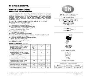
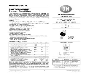
MBR2535CTL/D _ SWITCHMODE Power Rectifier ... employing the Schottky Barrier principle in a large metaltosilicon power MBR2535CTL diode. State-of-the-art geometry features epitaxial construction with oxide passivation and metal overlay contact. Ideally suited for use in low voltage, high frequency switching power supplies, free wheeling diodes, and polarity protection diodes. e Very Low Forward Voltage (0.55 V Maximum @ 25 Amps) SCHOTTKY BARRIER e Matched Dual Die Construction (12.5 A per Leg or 25 A per RECTIFIER Package) 25 AMPERES * Guardring for Stress Protection 35 VOLTS e Highly Stable Oxide Passivated Junction (125C Operating Junction Temperature) e Epoxy Meets UL94, VO at 1/8 Mechanical Characteristics e Case: Epoxy, Molded e Weight: 1.9 grams (approximately) e Finish: All External Surfaces Corrosion Resistant and Terminal 2,4 Leads are Readily Solderable 3 Lead Temperature for Soldering Purposes: 260C Max. for 10 Seconds CASE 221A-06 e Shipped 50 units per plastic tube (TO-220AC) e Marki
 4 Pages, 136 KB, Scan
pping TO-220 50 Units/Rail TO-220 (Pb-Free) 50 Units/Rail For information on tape and reel specifications, including part orientation and tape sizes, please refer to our Tape and Reel Packaging Specifications Brochure, BRD8011/D. Publication Order Number: MBR2535CTL/D MBR2535CTL THERMAL CHARACTERISTICS Characteristic Thermal Resistance, Junction-to-Case Symbol Max Unit RJC 2.0 C/W Symbol Max Unit ELECTRICAL CHARACTERISTICS (Per Leg) Characteristic Maximum Instantaneous Forward Voltage (Note 1) (IF = 25 Amps, TJ = 25C) (IF = 12.5 Amps, TJ = 25C) (IF = 12.5 Amps, TJ = 125C) VF Maximum Instantaneous Reverse Current (Note 1) (Rated dc Voltage, TJ = 25C) (Rated dc Voltage, TJ = 125C) IR 50 IF, INSTANEOUS FORWARD CURRENT (AMP) 20 TJ = 125C 10 5 TJ = 25C 2 1 0.5 0.2 0.1 0.1 mA 5.0 500 1. Pulse Test: Pulse Width = 300 s, Duty Cycle 2.0%. 0 V 0.55 0.47 0.41 0.2 0.3 0.4 0.5 0.6 0.7 0.8 vF, INSTANTANEOUS VOLTAGE (VOLTS) Figure 1. Typical Forward Voltage, Per Leg http://onsemi.com 2 0.9 10 1000 IR , REVERSE
 4 Pages, 47 KB, Original
MBR2535CTL/D SEMICONDUCTOR (a TECHNICAL DATA " T-03-17 MOTOROLA SC (DIODES/OPTO) 359E D ES 6367255 0083050 0 EAMNOT? Swiichmode MBR2535CTL Power Rectifiers | MBR2530CTL ... employing the Schottky Barrier principle in a large metal-to-silicon power diode. State-of-the-art geometry features epitaxial construction with oxide passivation and metal overlay contact. Ideally suited for use in low voltage, high frequency switching power supplies, SCHOTTKY BARRIER free wheeling diodes, and polarity protection diodes. RECTIFIERS e Very Low Forward Voltage (0.55 V Maximum @ 25 Amps) 25 AMPERES Matched Dual Die Construction (12.5 A per Leg or 25 A per Package) 30 and 35 VOLTS e Guardring for Stress Protection e Highly Stable Oxide Passivated Junction (125C Operating Junction Temperature) Epoxy Meets UL94, VO at 1/8 CASE 221A-06 (TO-220AC) MAXIMUM RATINGS (PER LEG) Rating Symbol MBR2535CTL | MBR2530CTL Unit Peak Repetitive Reverse Voltage VRRM 40 35 Volts Working Peak Reverse Voltage VRWM 35 30 DC Blocking Vo
 3 Pages, 275 KB, Scan
Avalanche Energy Waval 20 mJ Rating Semiconductor Components Industries, LLC, 2000 October, 2000 - Rev. 2 195 TO-220AB CASE 221A PLASTIC MARKING DIAGRAM ORDERING INFORMATION Device MBR2535CTL Package Shipping TO-220 50 Units/Rail Publication Order Number: MBR2535CTL/D MBR2535CTL THERMAL CHARACTERISTICS Characteristic Thermal Resistance -- Junction to Case Symbol Max Unit RJC 2.0 C/W ELECTRICAL CHARACTERISTICS (Per Leg) Maximum Instantaneous Forward Voltage (Note 1.) (IF = 25 Amps, TJ = 25C) (IF = 12.5 Amps, TJ = 25C) (IF = 12.5 Amps, TJ = 125C) VF Maximum Instantaneous Reverse Current (Note 1.) (Rated dc Voltage, TJ = 25C) (Rated dc Voltage, TJ = 125C) IR Volts 0.55 0.47 0.41 mA 5.0 500 1. Pulse Test: Pulse Width = 300 s, Duty Cycle 2.0%. ""',-'(.,(+0+.++'-&) -# -# K "',-'-'(., /(%- /(%-, Figure 1. Typical Forward Voltage, Per Leg http://onsemi.com 196 -# "+/+,.++'-B + -# -# /+ +/+, /(%- /(%-, )/+ (+0+)(0+",,")-"('0--, / MBR2535CTL -# ,*.+ 0/ ,"' 0/ +,",-"/ %( 98 "/+ (+0+.++'-&), / "/+ (+0+.++'-&
 578 Pages, 6112 KB, Original
ange Operating Junction Temperature Semiconductor Components Industries, LLC, 2000 October, 2000 - Rev. 2 124 TO-220AB CASE 221A PLASTIC MARKING DIAGRAM ORDERING INFORMATION Device MBR2535CTL Package Shipping TO-220 50 Units/Rail Publication Order Number: MBR2535CTL/D MBR2535CTL THERMAL CHARACTERISTICS Characteristic Thermal Resistance -- Junction to Case Symbol Max Unit RJC 2.0 C/W ELECTRICAL CHARACTERISTICS (Per Leg) Maximum Instantaneous Forward Voltage (Note 1.) (IF = 25 Amps, TJ = 25C) (IF = 12.5 Amps, TJ = 25C) (IF = 12.5 Amps, TJ = 125C) VF Maximum Instantaneous Reverse Current (Note 1.) (Rated dc Voltage, TJ = 25C) (Rated dc Voltage, TJ = 125C) IR Volts 0.55 0.47 0.41 mA 5.0 500 1. Pulse Test: Pulse Width = 300 s, Duty Cycle 2.0%. 50 IF, INSTANEOUS FORWARD CURRENT (AMP) 20 TJ = 125C 10 5 TJ = 25C 2 1 0.5 0.2 0.1 0 0.1 0.2 0.3 0.4 0.5 0.6 0.7 0.8 vF, INSTANTANEOUS VOLTAGE (VOLTS) Figure 1. Typical Forward Voltage, Per Leg http://onsemi.com 125 0.9 10 PF(AV), AVERAGE FORWARD POWER DISSIPATI
 3 Pages, 59 KB, Original
d the ON Semiconductor Soldering and Mounting Techniques Reference Manual, SOLDERRM/D. (c) Semiconductor Components Industries, LLC, 2015 January, 2015 - Rev. 6 1 Device Package Shipping MBR2535CTLG TO-220 (Pb-Free) 50 Units/Rail Publication Order Number: MBR2535CTL/D MBR2535CTLG MAXIMUM RATINGS (Per Leg) Symbol Value Unit Peak Repetitive Reverse Voltage Working Peak Reverse Voltage DC Blocking Voltage VRRM VRWM VR 35 V Average Rectified Forward Current (TC = 142C per Diode) (TC = 142C per Device) IF(AV) Peak Repetitive Forward Current, per Leg (Sq Wave, 20 kHz, TC = 139C) IFRM 25 A Non-Repetitive Peak Surge Current (Surge Applied at Rated Load Conditions, Halfwave, Single Phase, 60 Hz) IFSM 150 A Peak Repetitive Reverse Surge Current (2.0 ms, 1.0 kHz) IRRM 1.0 A Storage Temperature Range Tstg -65 to +150 C Operating Junction Temperature (Note 1) TJ -65 to +150 C Voltage Rate of Change (Rated VR) dv/dt 10,000 V/ms Controlled Avalanche Energy Waval 20 mJ Rating A 12.5 25 Stresses exceeding those l
 5 Pages, 218 KB, Original


