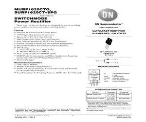
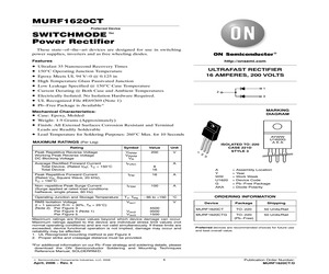
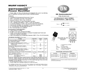
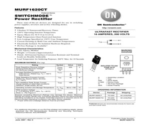
MURF1620CTG, SURF1620CT-SPG Preferred Device SWITCHMODE Power Rectifier These state-of-the-art devices are designed for use in switching power supplies, inverters and as free wheeling diodes. Features Ultrafast 35 Nanosecond Recovery Times 150C Operating Junction Temperature Epoxy Meets UL 94 V-0 @ 0.125 in High Temperature Glass Passivated Junction Low Leakage Specified @ 150C Case Temperature Current Derating @ Both Case and Ambient Temperatures Electrically Isolated. No Isolation Hardware Required. ESD Rating: Human Body Model = 3B (> 8 kV) Machine Model = C (> 400 V) AEC-Q101 Qualified and PPAP Capable SURF Prefix for Automotive and Other Applications Requiring Unique Site and Control Change Requirements Pb-Free Package* http://onsemi.com ULTRAFAST RECTIFIER 16 AMPERES, 200 VOLTS ISOLATED TO-220 CASE 221D STYLE 3 1 2 Mechanical Characteristics: 3 Case: Epoxy, Molded Weight: 1.9 Grams (Approximately) Finish: All External Surfaces Corrosion Resistant and Terminal MARKING DIAGRAM Leads are Readi
 4 Pages, 124 KB, Original
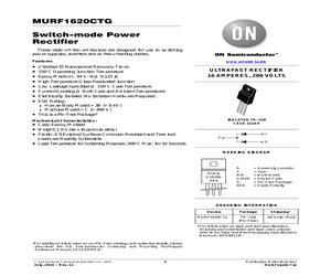
MURF1620CTG Switch-mode Power Rectifier These state-of-the-art devices are designed for use in switching power supplies, inverters and as free wheeling diodes. Features * * * * * * * * * www.onsemi.com Ultrafast 35 Nanosecond Recovery Times 150C Operating Junction Temperature Epoxy Meets UL 94 V-0 @ 0.125 in High Temperature Glass Passivated Junction Low Leakage Specified @ 150C Case Temperature Current Derating @ Both Case and Ambient Temperatures Electrically Isolated. No Isolation Hardware Required. ESD Rating: Human Body Model = 3B (> 8 kV) Machine Model = C (> 400 V) This is a Pb-Free Package* ULTRAFAST RECTIFIER 16 AMPERES, 200 VOLTS ISOLATED TO-220 CASE 221AH Mechanical Characteristics: * Case: Epoxy, Molded * Weight: 1.9 Grams (Approximately) * Finish: All External Surfaces Corrosion Resistant and Terminal Leads are Readily Solderable 1 2 * Lead Temperature for Soldering Purposes: 260C Max. for 10 Seconds 3 MARKING DIAGRAM AYWW U1620G AKA A Y WW U1620 G AKA = Assembly Location = Year = Wo
 4 Pages, 57 KB, Original
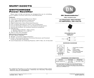
MURF1620CTG SWITCHMODE Power Rectifier These state-of-the-art devices are designed for use in switching power supplies, inverters and as free wheeling diodes. Features * * * * * * * * * http://onsemi.com Ultrafast 35 Nanosecond Recovery Times 150C Operating Junction Temperature Epoxy Meets UL 94 V-0 @ 0.125 in High Temperature Glass Passivated Junction Low Leakage Specified @ 150C Case Temperature Current Derating @ Both Case and Ambient Temperatures Electrically Isolated. No Isolation Hardware Required. ESD Rating: Human Body Model = 3B (> 8 kV) Machine Model = C (> 400 V) This is a Pb-Free Package* ULTRAFAST RECTIFIER 16 AMPERES, 200 VOLTS ISOLATED TO-220 CASE 221D STYLE 3 Mechanical Characteristics: * Case: Epoxy, Molded * Weight: 1.9 Grams (Approximately) * Finish: All External Surfaces Corrosion Resistant and Terminal Leads are Readily Solderable 1 2 3 * Lead Temperature for Soldering Purposes: 260C Max. for 10 Seconds MARKING DIAGRAM AYWW U1620G AKA A Y WW U1620 G AKA = Assembly Location =
 3 Pages, 85 KB, Original
MURF1620CTG Switch-mode Power Rectifier These state-of-the-art devices are designed for use in switching power supplies, inverters and as free wheeling diodes. Features * * * * * * * * * www.onsemi.com Ultrafast 35 Nanosecond Recovery Times 150C Operating Junction Temperature Epoxy Meets UL 94 V-0 @ 0.125 in High Temperature Glass Passivated Junction Low Leakage Specified @ 150C Case Temperature Current Derating @ Both Case and Ambient Temperatures Electrically Isolated. No Isolation Hardware Required. ESD Rating: Human Body Model = 3B (> 8 kV) Machine Model = C (> 400 V) This is a Pb-Free Package* ULTRAFAST RECTIFIER 16 AMPERES, 200 VOLTS ISOLATED TO-220 CASE 221AH Mechanical Characteristics: * Case: Epoxy, Molded * Weight: 1.9 Grams (Approximately) * Finish: All External Surfaces Corrosion Resistant and Terminal Leads are Readily Solderable 1 2 * Lead Temperature for Soldering Purposes: 260C Max. for 10 Seconds 3 MARKING DIAGRAM AYWW U1620G AKA A Y WW U1620 G AKA = Assembly Location = Year = Wo
 3 Pages, 50 KB, Original
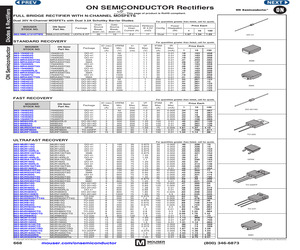
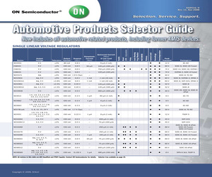
 863-MUR4100EG 863-MUR550PFG 863-MUR620CTG 863-MUR810G 863-MUR815G 863-MUR820G 863-MURD620CTT4G 863-MURH840CTG 863-MUR860G 863-MUR880EG 863-MURH860CTG 863-MURHF860CTG 863-MUR1510G 863-MUR1520G 863-MUR1560G 863-MUR1610CTG 863-MUR1620CTG 863-MUR1620CTRG 863-MURF1620CTG 863-MUR1640CTG 863-MUR2020RG 863-MUR3020PTG 863-MUR3020WTG 863-MUR3040PTG 863-MUR3060PTG 863-MURS260T3G 863-MURS320T3G 863-MURS360T3G (c) Copyright 2011 Mouser Electronics 25 100 500 .078 .078 .078 .051 .078 .051 .078 .051 .085 .051 .078 .043 .17 .085 .191 .191 .127 .191 .055 .055 .055 .049 .055 .043 .055 .043 .055 .049 .055 .041 .118 .067 .118 .118 .118 .118 .042 .042 .042 .047 .042 .038 .042 .038 .042 .047 .042 .039 .095 .054 .095 .095 .095 .095 DO-41 SMB SMA For quantities of 1000 and up, call for quote. ON Semi Part No. 1N4934G 1N4935G 1N4936G 1N4937G MR854G MR856G Package DO-41 DO-41 DO-41 DO-41 DO-201AD DO-201AD IO (rec) VRRM Max. Min. (A) (V) 1 1 1 1 3 3 100 200 400 600 400 600 VFM IFSM trr Max. Max. Max. (A) (V) (ns) ON Semi
 379 Pages, 47721 KB, Original
G 863-MUR480EG 863-MUR4100EG 863-MUR620CTG 863-MURD620CTT4G 863-MUR810G 863-MUR815G 863-MUR820G 863-MURH840CTG 863-MUR860G 863-MURH860CTG 863-MURHF860CTG 863-MUR880EG 863-MUR1510G 863-MUR1520G 863-MUR1560G 863-MUR1610CTG 863-MUR1620CTG 863-MUR1620CTRG 863-MURF1620CTG 863-MUR1640CTG 863-MUR2020RG 863-MUR3020WTG Price Each Continuous RDS(on) Power Drain @ 4.5V Config. Dissipation Current (A) (m) (W) MUR110G MUR115G MUR120G MUR120RLG MURS120T3G MUR140G MUR140RLG MURA140T3G MUR160G MUR160RLG MURS160T3G MUR180EG MURA210T3G MURS220T3G MUR260G MURS260T3G MURS320T3G MURS360T3G MUR410G MUR415G MUR460G MUR460RLG MUR480EG MUR4100EG MUR620CTG MURD620CTT4G MUR810G MUR815G MUR820G MURH840CTG MUR860G MURH860CTG MURHF860CTG MUR880EG MUR1510G MUR1520G MUR1560G MUR1610CTG MUR1620CTG MUR1620CTRG MURF1620CTG MUR1640CTG MUR2020RG MUR3020WTG mouser.com/onsemiconductor IR Max. (mA) 0.005 0.005 0.005 0.005 0.005 0.01 0.01 0.01 0.005 0.01 0.01 Price Each 1 .24 .24 .24 .22 .22 .45 .45 .45 1.61 .93 1.34 10 .16
 1 Pages, 311 KB, Original
01 0.005 0.005 0.005 0.25 0.5 0.005 0.5 0.5 LMUR1620CTRG 16 85 200 1.2 100 0.005 Package Dimensions 1 2,4 3 STYLE 4 1 2 3 Package 1 2,4 3 64 STYLE Leshan Radio Company, Ltd. 2008 PRODUCTS CATALOGUE 10. TO-220FP Ultrafast Rectifiers Device I O(rec) Max(A) LMURF1620CTG 16 LMURF1660CTG 16 LMURHF860CTG 8 t rr Max(ns) 25 60 35 VRRM Min(V) 200 600 600 V FM Max(V) 0.975 1.5 2.8 I FSM IR Max(A) Max(mA) 100 100 100 0.005 0.5 0.5 Package Dimensions 1 2 3 STYLE 1 2 3 Package 11. TO-220AC Soft Ultrafast Rectifiers Device LMSR1560G LMSR860G I O(rec) Max(A) 15 8 t rr Max(ns) 45 120 VRRM Min(V) 600 600 V FM Max(V) 1.8 1.7 I FSM Max(A) 100 100 IR Package Dimensions Max(mA) 0.015 0.01 1,4 STYLE 3 4 1 3 Package 65 Leshan Radio Company, Ltd. http//:www.lrc.cn 12. 0.2A High Voltage Rectifiers Device Maximum Average Maximum Rectified Current Peak @ Half-Wave Reverse Resistive Load Voltage 60Hz IO @ TL PRV A AV V PK R1200 R1500 R1800 R2000 R3000 R4000 R5000 1200 1500 1800 2000 3000 4000 5000 0.2 0.2 0.2 0.2 0.2 0.2 0.
 225 Pages, 6963 KB, Original
oHS COMPLIANT -- ULTRA-FAST RECTIFIERS IO @ TA Mfg. Part No. MUR120G MUR160G MUR180EG MUR480EG MUR420G MUR460G MUR4100EG MUR620CTG MUR820G MUR840G MUR860G MUR880EG MUR8100EG MURH840CTG MURH860CTG MUR1520G MUR1540G MUR1560G MUR1620CTG MUR1640CTG MUR1660CTG MURF1620CTG* MUR3060WTG MUR3020PTG MUR3040PTG Axial Lead Button DO-201AD VRRM (V) (A) (C) 200 1 130 600 1 120 800 1 95 800 4 35 200 4 80 600 4 40 1000 4 35 200 6 130 200 8 150 400 8 150 600 8 150 800 8 175 1000 8 150 400 8 130 600 8 120 200 15 150 400 15 150 600 15 145 200 16 150 400 16 150 600 16 150 200 16 150 600 30 145 200 30 150 400 30 150 TO-220AC VF Max. @ IF TC=25C (V) 0.875 @ 1A 1.25 @ 1A 1.5 @ 1A 1.75 @ 3A 0.875 @ 3A 1.25 @ 3A 1.75 @ 3A 0.975 @ 3A 0.975 @ 8A 1.3 @ 8A 1.50 @ 8A 1.80 @ 8A 1.80 @ 8A 2.0 @ 4A 2.8 @ 4A 1.05 @ 15A 1.25 @ 15A 1.50 @ 15A 0.975 @ 8A 1.3 @ 8A 1.5 @ 8A 0.975 @ 8A 1.25 @ 15A 1.12 @ 15A 1.25 @ 15A TO-247 Price Each IFSM (A) 35 35 35 70 125 70 70 75 100 100 100 100 100 100 100 200 150 150 100 100 100 100 150 200 400
 375 Pages, 58008 KB, Original
 TJ, Tstg - 65 to +150 C ORDERING INFORMATION Operating Junction and Storage Temperature RMS Isolation Voltage (t = 1 second, R.H. 30%, TA = 25C) (Note 2) Per Figure 3 Per Figure 4 (Note 1) Per Figure 5 Viso1 Viso2 Viso3 V 4500 3500 1500 Device MURF1620CT MURF1620CTG Maximum ratings are those values beyond which device damage can occur. Maximum ratings applied to the device are individual stress limit values (not normal operating conditions) and are not valid simultaneously. If these limits are exceeded, device functional operation is not implied, damage may occur and reliability may be affected. 1. UL Recognized mounting method is per Figure 4 2. Proper strike and creepage distance must be provided. = Assembly Location = Year = Work Week = Device Code = Pb-Free Package = Diode Polarity Package Shipping TO-220 50 Units/Rail TO-220 (Pb-Free) 50 Units/Rail Preferred devices are recommended choices for future use and best overall value. *For additional information on our Pb-Free strategy and solderi
 4 Pages, 109 KB, Original
perating Conditions may affect device reliability. 1. Proper strike and creepage distance must be provided. = Assembly Location = Year = Work Week = Device Code = Pb-Free Package = Diode Polarity ORDERING INFORMATION Device 4500 AYWW U1620G AKA MURF1620CT MURF1620CTG Package Shipping TO-220 50 Units/Rail TO-220 (Pb-Free) 50 Units/Rail Preferred devices are recommended choices for future use and best overall value. *For additional information on our Pb-Free strategy and soldering details, please download the ON Semiconductor Soldering and Mounting Techniques Reference Manual, SOLDERRM/D. (c) Semiconductor Components Industries, LLC, 2008 September, 2008 - Rev. 7 1 Publication Order Number: MURF1620CT/D MURF1620CT THERMAL CHARACTERISTICS (Per Leg) Rating Maximum Thermal Resistance, Junction-to-Case Symbol Value Unit RqJC 4.2 C/W TL 260 C Symbol Value Unit Lead Temperature for Soldering Purposes: 1/8 from the Case for 5 seconds ELECTRICAL CHARACTERISTICS (Per Leg) Characteristic Maximum Instantaneou
 4 Pages, 91 KB, Original
1 SMB MURD320T4G 200 3 0.95 0.5 75 35 Note 1 DPAK-4 MURS320T3G 200 3 0.875 0.005 75 35 Note 2 SMC MURD620CTT4G 200 6 1.2 0.005 63 35 Note 1 DPAK-4 MURB1620CTRT4G 200 16 1.2 0.005 100 85 Note 1 D2PAK-3 MURB1620CTT4G 200 16 0.975 0.005 100 35 Note 1 D2PAK-3 MURF1620CTG 200 16 0.975 0.005 100 25 Note 2 TO-220 FP MURA140T3G 400 1 1.1 0.005 35 65 Note 1 SMA MURS160T3G 600 1 1.25 0.005 35 75 Note 2 SMB MURS360T3G 600 3 1.25 0.01 75 75 Note 2 SMC NOTE 1: Devices are AEC-Qualified and PPAP-Capable. Contact ON Semiconductor for details. NOTE 2: Contact ON Semiconductor for AEC and PPAP status. SCHOTTKY RECTIFIERS VRRM Min (V) IO(rec) Max (A) VF Max (V) IRM Max (A) IFSM Max (A) AEC-PPAP MBRD620CTT4G Device 20 6 0.9 100 75 Note 1 Package DPAK-4 MBR0530T1G 30 0.5 0.43 130 5.5 Note 1 SOD-123 MBRS130LT3G 30 1 0.395 1000 40 Note 1 SMB MBRD1035CTLT4G 35 10 0.56 2000 50 Note 1 DPAK-4 MBR140SFT1G 40 1 0.55 500 30 Note 1 SOD-123 FL SMB MBRS140T3G 40 1 0.6 1000 40 Note 1 MBRA340T3G 40 3 0.45 300 100 Note 1 SMA MBRD3
 20 Pages, 390 KB, Original
 TJ, Tstg - 65 to +150 C ORDERING INFORMATION Operating Junction and Storage Temperature RMS Isolation Voltage (t = 1 second, R.H. 30%, TA = 25C) (Note 2) Per Figure 3 Per Figure 4 (Note 1) Per Figure 5 Viso1 Viso2 Viso3 V 4500 3500 1500 Device MURF1620CT MURF1620CTG Maximum ratings are those values beyond which device damage can occur. Maximum ratings applied to the device are individual stress limit values (not normal operating conditions) and are not valid simultaneously. If these limits are exceeded, device functional operation is not implied, damage may occur and reliability may be affected. 1. UL Recognized mounting method is per Figure 4 2. Proper strike and creepage distance must be provided. = Assembly Location = Year = Work Week = Device Code = Pb-Free Package = Diode Polarity Package Shipping TO-220 50 Units/Rail TO-220 (Pb-Free) 50 Units/Rail Preferred devices are recommended choices for future use and best overall value. *For additional information on our Pb-Free strategy and solderi
 4 Pages, 59 KB, Original
nded exposure to stresses above the Recommended Operating Conditions may affect device reliability. 1. Proper strike and creepage distance must be provided. = Assembly Location = Year = Work Week = Device Code = Pb-Free Package = Diode Polarity MURF1620CT MURF1620CTG Package Shipping TO-220 50 Units/Rail TO-220 (Pb-Free) 50 Units/Rail Preferred devices are recommended choices for future use and best overall value. *For additional information on our Pb-Free strategy and soldering details, please download the ON Semiconductor Soldering and Mounting Techniques Reference Manual, SOLDERRM/D. (c) Semiconductor Components Industries, LLC, 2007 June, 2007 - Rev. 6 1 Publication Order Number: MURF1620CT/D MURF1620CT THERMAL CHARACTERISTICS (Per Leg) Rating Maximum Thermal Resistance, Junction-to-Case Symbol Value Unit RqJC 4.2 C/W TL 260 C Symbol Value Unit Lead Temperature for Soldering Purposes: 1/8 from the Case for 5 seconds ELECTRICAL CHARACTERISTICS (Per Leg) Characteristic Maximum Instantaneous For
 4 Pages, 75 KB, Original


